Applicable Operating Conditions
This configuration is suitable for process liquids that exhibit good fluidity at ambient temperatures and can be pumped steadily, such as certain beverage bases, edible oils, seasoning liquids, pharmaceutical solutions, cleaning fluids, cooling fluids, and low-viscosity chemical fluids. Whether the pipeline magnetic rod assembly can be adopted directly still depends on confirming factors such as corrosivity, hygiene requirements, impurity characteristics, and pressure conditions.
Three Common Installation Locations
After unloading or at the tank inlet
Used to detect magnetic foreign objects that may be introduced via external containers, tank trucks, hoses, and quick-connect couplings. The equipment should match the unloading flow rate and interface specifications, avoid significantly prolonging the unloading time, and provide sufficient space for disassembly and cleaning.
At the pump inlet or outlet
Installing at the pump inlet can provide early protection for the pump and valves, but pressure drop must be carefully controlled to avoid compromising suction conditions; at the pump outlet, the pressure is generally more stable, making it easier to employ a closed-loop pipeline filtration system. The final location should be selected based on the pump type, pipeline resistance, pressure pulsations, and maintenance considerations.
Before filtration, heat exchange, or filling equipment
Installing near the end point can capture iron filings, rust flakes, and some wear particles generated by process equipment, thereby protecting nozzles or filling valves. If finished-product control also includes non-magnetic metals, an independent detection step should be added rather than simply increasing the surface field strength of the magnetic rods.
Key Points in Structural Assessment
- Flow Path and Pressure Drop:The shell design and magnetic-rod arrangement should be determined according to flow rate, pipe diameter, and viscosity; simply increasing the number of magnetic rods is not advisable.
- Connections and Sealing:Flanged, clamp, threaded, or welded connections should be consistent with existing piping and cleaning requirements.
- Contact Materials:Assess 304, 316L, coatings, and seals based on corrosion, food-contact, or cleanliness requirements.
- Cleaning Methods:When impurity loading is low, manual cleaning may suffice; for higher-frequency operation, consider sleeve separation, automated extraction, or flush-and-drain options.
- Installation Orientation:Horizontal, vertical, or inclined installation affects drainage, sedimentation, and maintenance accessibility; the orientation should be determined in conjunction with the flow direction.
Hygiene and CIP: “Washable” Is Not Enough
For production lines requiring CIP, it is essential to verify internal surfaces, welds, seals, drainage capability, dead zones, cleaning-fluid temperature, flow rate, and washing sequence. A standard easy-to-disassemble and clean structure does not automatically meet a specific hygiene or CIP standard; during project confirmation, the applicable standards and acceptance criteria should be clearly defined.
Information Required from the Customer
Please provide the liquid name, temperature, viscosity, normal and peak flow rates, pipe diameter, operating pressure, photos or composition of impurities, installation location, interface standards, cleaning frequency, and acceptable downtime. These parameters will be used to determine the number of magnetic rods, flow path, materials, and cleaning strategy.
Structural and Principle Diagrams
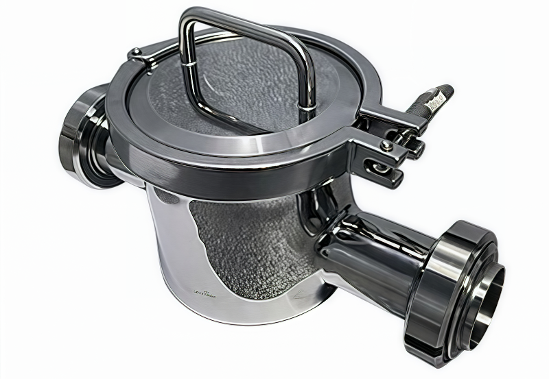
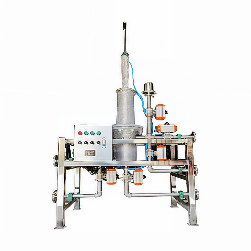
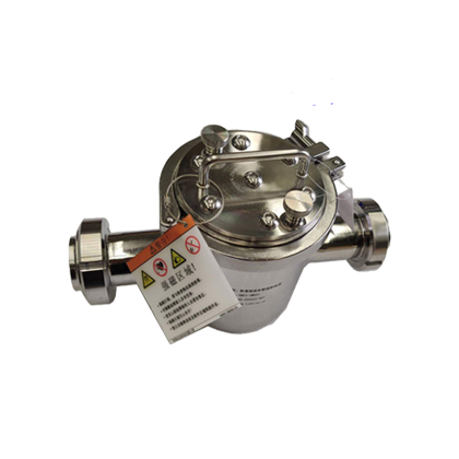
The following are our company’s existing equipment, internal structures, and working-principle documentation, intended to aid in understanding the applicable configurations, combinations, and installation methods. The final configuration must still be confirmed in light of the material properties, flow rate, installation space, and cleaning requirements.