When is a mobile circulation system appropriate?
A mobile cart can be used to establish a temporary or permanent recirculation loop when a workshop has multiple storage tanks, production batches are discontinuous, there is insufficient space for retrofitting fixed piping, or when you wish to first verify the effectiveness of magnetic filtration. The equipment typically consists of a pump, a magnetic filtration unit, valves, flexible or rigid tubing, drain connections, and a mobile chassis.
Typical operating procedure
- Ensure that the material in the storage tank has been thoroughly mixed, and select a representative suction inlet location.
- Connect the suction and return lines, and inspect the valves, grounding, air supply, or power supply.
- Start the pump at low speed to purge the air from the lines and observe for leaks, pulsation, and pressure drop.
- Process according to the set time or recirculation volume, while maintaining mixing within the tank.
- Take samples from the designated locations to determine whether to continue recirculation, switch equipment, or conclude the treatment.
- Drain and recover the qualified material, remove the magnetic contaminants, and complete the batch-change cleaning.
System configuration must be tailored to the material
- Pump:Pneumatic diaphragm pumps, electric pumps, or the customer’s existing pumps must match the slurry’s viscosity, particle size, shear sensitivity, and explosion-proof requirements.
- Magnetic filtration unit:Select single-stage, multi-stage, easy-to-clean, or post-electromagnetic units based on the type and size of contaminants, flow rate, and cleaning frequency.
- Piping and valves:Flexible hoses offer greater mobility, while rigid piping provides greater stability; both must account for pressure resistance, corrosion resistance, complete drainage, and ease of cleaning.
- Control:Flow rate, pressure, run time, number of cycles, fault alarms, and PLC interlocks can be discussed.
- Mobile structure:Chassis dimensions, caster load capacity, push path, hose storage, and equipment center of gravity must all be suitable for the site conditions.
The number of recirculation cycles does not equate to treatment effectiveness
If the tank contents are not adequately mixed, the equipment may repeatedly process the same layer of liquid near the surface, while the slurry settled at the bottom remains outside the recirculation loop. A comprehensive assessment should be based on the tank volume, actual flow rate, mixing condition, and sampling results; relying solely on “how many cycles” as an acceptance criterion is not advisable.
Batch change and cross-contamination
When switching between food, pharmaceutical, fine chemical, and differently colored slurries, residual control must be clearly defined for hoses, pump chambers, magnetic rod sleeves, valves, and low-point drains. Options such as dedicated carts, detachable piping, rinse-and-recovery systems, or cleaning validation can be evaluated to prevent residues from the previous batch from contaminating the next.
How to choose between mobile and fixed solutions
Mobile recirculation is ideal for flexible use and initial verification; however, as batch volumes increase, flow rates rise steadily, cleaning becomes more frequent, or full interlocking is required, fixed piping, automated cleaning, or high-gradient electromagnetic systems are usually more conducive to standardization. Both parties can gradually upgrade based on production capacity and actual operating records.
Structural and schematic diagrams
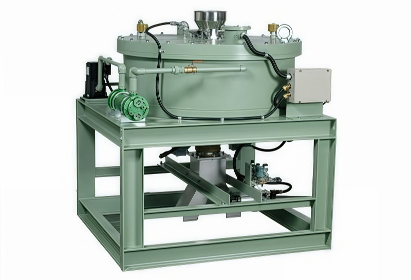
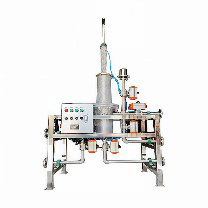
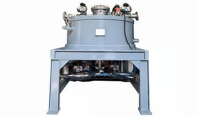
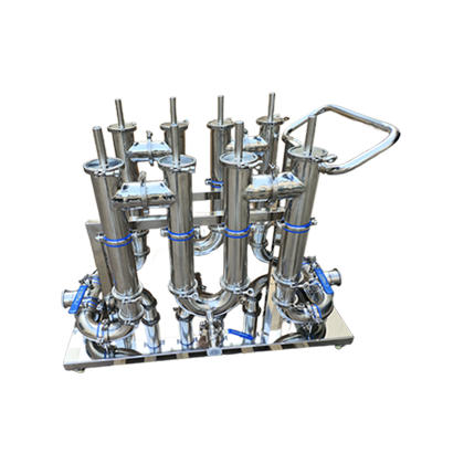
The following materials present the company’s existing equipment, internal structures, and operating principles, serving as reference to help understand the available configurations, combinations, and installation options. The final configuration, however, must still be confirmed in light of the material properties, flow rate, installation space, and cleaning requirements.