Magnetic separation and metal detection are not the same type of equipment.
Magnetic grates, drawer magnets, and other magnetic separators continuously adsorb impurities that are affected by magnetic fields; they feature a simple design and can be deployed at multiple points in the production process. Metal detectors identify metallic contaminants in the product stream using electromagnetic signals, enabling the detection of non-magnetic metals and triggering rejection, alarms, or machine shutdowns.
The two technologies can be combined, but they cannot fully replace one another, nor should “metal detection” be interpreted as an inspection for all types of foreign objects, such as stones, glass, or plastics.
Why is pre-packaging an ideal location for combined inspection?
By the time products reach the pre-packaging stage, crushing, blending, and conveying have typically been completed, making this a critical point for controlling equipment wear debris and conducting final batch inspections. Equipment installed at this location must align with the packaging line’s cycle time, drop height, product effects, rejection space, and quality documentation requirements.
A common division of responsibilities
Step 1: Continuous magnetic separation for ferrous contaminant removal
Install easily cleaned magnetic grates, drawer magnets, or self-cleaning units at the discharge of the finished-product silo or above the packaging machine to continuously capture ferromagnetic contaminants. The collected magnetic particles can also be analyzed to trace impurity sources and assess equipment wear trends.
Step 2: Metal detection and response
Deploy metal detectors suitable for powders in free-fall sections. Upon detecting an anomaly, operators can choose among rapid flip gates, diverting valves, machine shutdowns, or alarms, depending on the production process. Rejection mechanisms must account for powder flow characteristics to prevent bridging, misdischarge, and secondary contamination.
Step 3: Control and documentation
Based on customer requirements, discuss testing procedures, alarm thresholds, rejection confirmation, access permissions, batch records, and interlocks with the packaging machine’s PLC. Communication protocols, data retention, and remote functionality are subject to project-specific validation.
Examples of installation locations
- Finished-product silo discharge:Space is usually compact, making it well-suited for magnetic separation while protecting downstream packaging equipment.
- Above the packaging machine:Close to the final product, ideal for final inspection, though available height and maintenance access may be limited.
- Blender discharge:Early detection of blender wear debris is possible, but subsequent conveying may reintroduce contaminants.
- Common header for multiple packaging lines:A basic control system can be installed on the header, with independent final inspections added on key packaging lines.
Detection performance requires on-site verification
Metal detector sensitivity is influenced by pipe diameter, product effects, flow velocity, metal type, shape, and orientation; magnetic separator effectiveness depends on material contact, magnetic field gradient, and cleaning status. Acceptance testing should be conducted using mutually agreed test samples, test locations, and procedures, rather than relying on fixed, generalized sensitivity claims posted online.
Jointly confirmed documentation
Packaging speed, per-package weight, powder temperature and flowability, chute diameter, available headroom, target metal types, test sample requirements, allowable rejection levels, anomaly-handling logic, cleaning methods, and batch-record specifications.
Structural and schematic diagrams
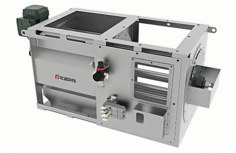
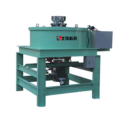
The following materials present the company’s existing equipment, internal configurations, and operating principles, serving as references to help understand applicable designs, combinations, and installation options. The final configuration, however, must still be determined in conjunction with material properties, flow rates, installation constraints, and cleaning requirements.