Application Objectives Precede Equipment Selection
Projects involving quartz sand, ceramic granules, glass raw materials, abrasives, and other mineral particles may aim to protect crushing and screening equipment, remove extraneous ferrous contaminants, reduce iron contamination introduced by equipment wear, or control specific magnetic fractions. Different objectives entail varying requirements for magnetic field reach, feed thickness, processing stages, and iron discharge methods.
Weakly magnetic impurities, inclusions, and minerals with particle sizes close to those of the target material are not equivalent to ordinary ferromagnetic foreign objects. Whether a permanent magnet head pulley, a high-intensity magnetic drum, a roller-type separator, or an electromagnetic route is suitable should be determined based on mineral properties and sample testing, rather than relying solely on the material name to guarantee final grade or purity.
Typical Process Locations
- Before Crushing and Grinding:Prioritize removing larger ferrous objects to protect crushers, mills, and conveying equipment.
- After Screening:Particle-size classification helps stabilize the feed, facilitating discussions on magnetic separation conditions for different size fractions.
- After Vibratory Feeding:Controlling the layer thickness and width ensures more uniform material entry into the drum or other sorting zones.
- Between Multi-Stage Processing:Adjust subsequent routes based on the composition of the captured material at each stage, rather than simply repeating the same equipment.
- Before Packaging or Entering Downstream Processes:Control magnetic contaminants that reappear during equipment wear, maintenance, and handling.
Abrasion and Impact Require Separate Consideration
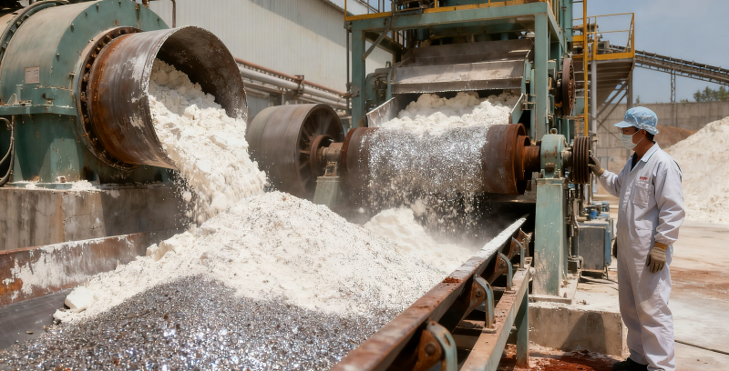
Quartz sand, corundum, glass cullet, and certain ores continuously erode casings, guide plates, drum surfaces, and discharge points. Structural design should account for liners or replaceable wear-resistant components, drop-height control, material impact angles, accumulation removal, and maintenance cycles. Wear-resistant measures may alter the distance between the material and the magnetic field, necessitating a balance between durability and separation performance.
Equipment Approaches for Continuous Processing
Magnetic Plates and Open Channels
Suitable for initially intercepting larger ferrous objects or reducing obstructions within the material flow, particularly in areas subject to significant impact, agglomeration, and wear. The angle of the magnetic plates, material trajectories, and cleaning methods must be confirmed in conjunction with the chute structure.
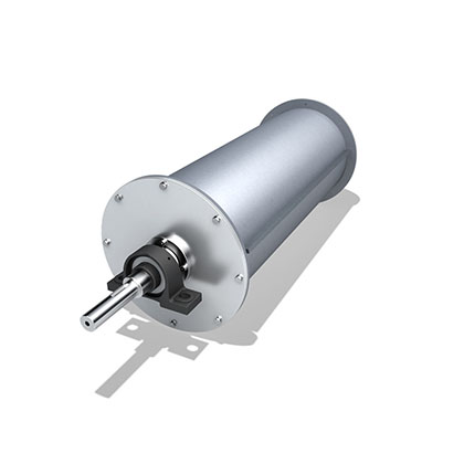
Magnetic Head Pulleys and Drum Magnetic Separators
Ideal for continuous feeding and continuous removal of magnetic materials. Stable results depend on feed width, material layer thickness, particle-size distribution, drum speed, discharge location, and material condition. When magnetic content is high, appropriate collection and anti-backmixing measures must also be designed.
Vibratory Feeders and Multi-Stage Magnetic Separation
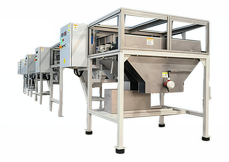
Vibratory feeders help control feed rate and material distribution, but the model, trough material, and wear-resistant design must be confirmed according to the specific material. For high-purity applications or the control of weakly magnetic impurities, staged processing, thin-layer feeding, and multi-stage routes can be considered; final parameters should be derived from sample testing or on-site validation.
What Customers Need to Provide
- Mineral name, source, particle-size distribution, maximum lump size, bulk density, and moisture content.
- Whether the objective is equipment protection, removal of extraneous ferrous contaminants, or control of a specific magnetic fraction.
- Samples of the raw material and target impurities, along with existing assay or analytical methods.
- Hourly throughput, continuous operation time, and existing screening and feeding equipment.
- Allowable material loss, wear-life targets, and maintenance requirements.
Verification and Acceptance Boundaries
It is recommended to first clarify sampling methods, evaluation criteria, and batch-to-batch material variations before deciding whether to conduct sample testing. Test results apply only to the corresponding samples, feed conditions, and equipment settings; when scaling up to the actual production line, flow rates, material distribution, installation environment, and continuous-operation conditions must be reconfirmed.
Structural and Principle Diagrams
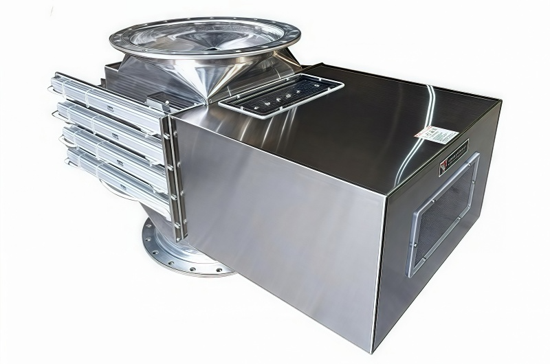
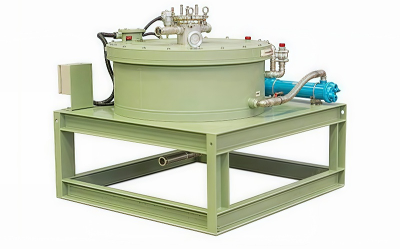
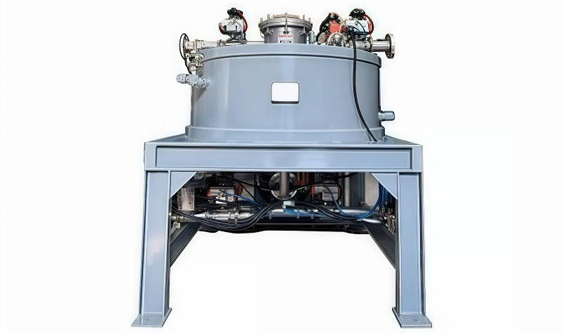
The following are the company’s existing equipment, internal structures, and working-principle documentation, intended to aid in understanding the available configurations, combinations, and installation options. The final configuration must still be confirmed in light of the material, throughput, installation space, and cleaning requirements.