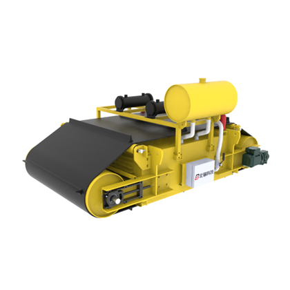
Why intercept ferrous contaminants early in heavy‑load conveying operations?
Ore, coal, aggregates, wood, biomass, and certain recyclables may contain embedded bolts, chains, steel plates, tools, wire, and worn‑out equipment components. If these large ferrous objects enter crushers, mills, screens, or downstream conveyors, they can cause blockages, surface damage, downtime, or belt failure.
In heavy‑load applications, the primary objective is not to capture extremely fine iron filings, but rather to ensure that large ferrous items enter the effective magnetic field at the appropriate location and exit cleanly from the main material stream. Equipment selection must be based on belt and material‑layer parameters, not merely on whether the device is “permanent magnet” or “electromagnetic.”
Preferred installation locations for evaluation
Head pulley discharge zone
As material leaves the belt at the head pulley, it tends to be relatively loose, and the trajectories of ferrous objects may differ from those of non‑magnetic materials, making this an ideal location for suspended magnets or magnetic head pulleys. Layout should consider the discharge trajectory, drop height, downstream chutes, and available separation space.
Above the mid‑section of the conveyor belt
Suitable for scenarios where interception equipment needs to be added to an existing conveyor line. Excessively thick material layers, excessive mounting heights, or target ferrous objects buried deep within the layer can all increase capture difficulty; lateral or longitudinal installation orientations also affect the direction of iron removal and spatial requirements.
Vibratory feeders and chute transfer points
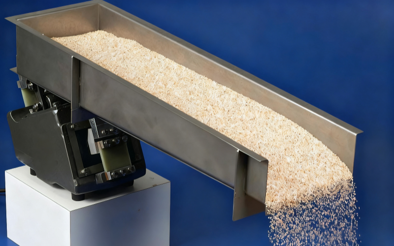
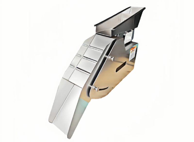
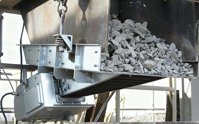
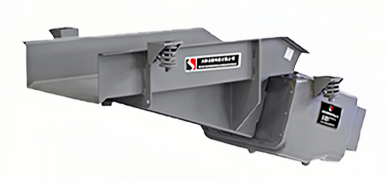
Feeding equipment can control flow rate and improve material distribution, while chute transfer points may cause material tumbling or thinning. Depending on the material trajectory, magnetic plates, suspended magnetic separators, or roller configurations can be considered, while avoiding the introduction of new blockage points.
Main equipment options
- Suspended permanent magnet separators:No excitation power supply is required, making them suitable for continuous magnetic field application; whether a self‑unloading design is adopted depends on the amount of captured material, cleaning frequency, and available space for iron removal.
- Suspended electromagnetic separators:Deeper material layers, greater mounting distances, or specific control requirements can be discussed on a project‑by‑project basis, but power supply, heat dissipation, duty cycle, and maintenance conditions must be confirmed.
- Magnetic head pulleys:Installed as the head pulley to provide continuous separation, ideal for new installations or projects with retrofitting potential; belt construction, wrap angle, and deflector plate positioning should be verified.
- Magnetic plates and chute structures:Suitable for transfer points, discharge locations, and channels handling large‑piece materials, with particular emphasis on assessing impact, wear, material accumulation, and safe cleaning practices.
Site data required for equipment selection
- Belt width, belt speed, trough angle, material layer thickness, and maximum instantaneous flow rate.
- Material bulk density, maximum lump size, moisture content, and adhesion characteristics.
- Material, dimensions, weight, shape, and potential burial depth of target ferrous objects.
- Installation height, structural steelwork, idler positions, and access for inspection and hoisting.
- Manual cleaning or automatic iron removal, continuous operating time, and interlock control requirements.
Forming a protective chain with downstream equipment
Suspended separators and magnetic head pulleys primarily handle ferromagnetic materials susceptible to magnetic forces. For metals that cannot be captured by magnetic separation, or for critical equipment requiring shutdown protection, further consideration can be given to metal detectors, alarms, belt stop systems, or bypass discharge. In recycling applications where aluminum, copper, and other non‑ferrous metals also need to be separated, pre‑separation of ferromagnetic metals and stable material distribution should be ensured before evaluating eddy current sorting routes.
Safety and maintenance
Suspended equipment requires reliable suspension and fall‑prevention measures, while moving parts, belts, and iron‑removal zones must be adequately guarded. Magnetic fields may interfere with tools, electronic devices, and personal belongings; electromagnetic devices must also be equipped with controls and protections in accordance with electrical standards. Cleaning, maintenance, and hoisting plans should be incorporated into on‑site confirmation prior to manufacturing.
Methods for solution validation
Please provide conveyor layout drawings or site photographs with dimensioned views, belt and material‑layer parameters, samples of target ferrous objects, and information on downstream equipment. Beisu can assist in comparing suspended permanent magnets, suspended electromagnets, magnetic head pulleys, and chute magnetic plates; the final model and installation configuration must be verified through engineering review.
Structural and principle diagrams
The following are the company’s existing equipment, internal structures, and working principles, intended to aid in understanding the applicable configurations, combinations, and installation methods. The final arrangement must still be confirmed in light of material properties, flow rates, installation space, and cleaning protocols.