First, confirm “smooth passage”
Free-flowing powders typically rely on gravity to pass through hoppers and vertical pipelines, but actual flow can still be affected by particle size, moisture content, static electricity, drop height, and instantaneous flow rate. Overly dense magnetic rod arrangements, uneven inlet distribution, or insufficient cleaning clearance can all reduce the equipment’s effective performance.
Representative installation locations
Manual dumping ports or small-bag feeding stations
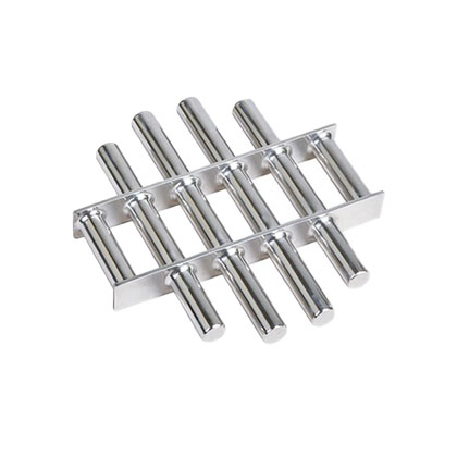
A magnetic grate can be installed beneath safety grates or dumping hoppers as a primary barrier at the feed end. For rapid cleaning, sleeve-equipped or easily accessible designs are recommended; in dusty environments, consider enclosed hoods, dust extraction interfaces, and adequate operator space.
Below ton‑bag unloaders and buffer bins
Ton‑bag unloaders may generate substantial instantaneous flow rates. Material can first be stabilized via a buffer bin or vibratory feeder before entering a drawer magnet or bullet magnet. If ferromagnetic contaminants are abundant, allow for cleaning frequency, iron‑collecting containers, and maintenance access.
Discharge points of silos or daily storage bins
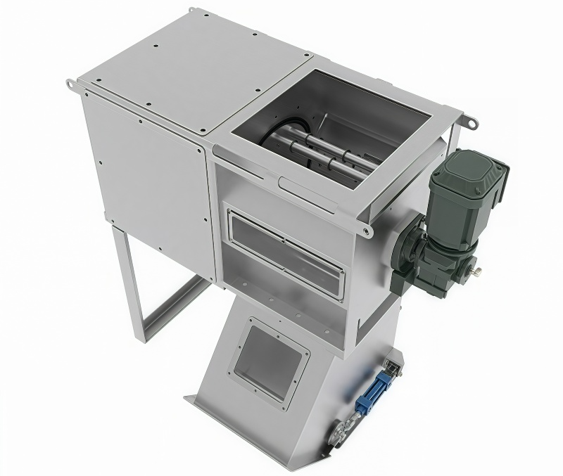
These locations are ideal for protecting weighing, blending, and packaging equipment. When manual access is convenient and cleaning intervals are long, a magnetic grate or standard drawer unit may be suitable; for elevated positions, frequent cleaning needs, or PLC integration, evaluate automated cleaning drawer designs.
Before packaging machines or finished‑goods bins
This is the final quality‑control point prior to packaging. Magnetic grates or drawer magnets continuously capture ferromagnetic impurities; if aluminum, copper, or other non‑magnetic metals also need to be detected, incorporate free‑fall metal detectors along with material‑specific reject mechanisms.
Structural selection should not depend solely on gauss values
- Whether the material flows uniformly past the magnetic rods rather than concentrating in gaps;
- Whether the number of rod layers, spacing, andDiversionstructure are appropriate for the flow rate and particle size;
- Whether manual cleaning, quick‑sleeve removal, or automatic iron discharge better aligns with the production rhythm;
- Whether disassembly directions, maintenance heights, and iron‑collection methods facilitate on‑site operation;
- Whether contact materials, surface treatments, sealing, and cleaning methods meet customer requirements.
A possible configuration combination
Magnetic grate at the dumping port → Buffer/supplemental feeding → Drawer magnet at the silo outlet → Metal detection before packaging
Front‑end control targets incoming foreign objects, mid‑range protection safeguards equipment, and the rear end performs quality inspection. In practice, projects may implement only one of these stages, or progress in phases based on risk and budget.
Please provide the following data
Material name, particle size and bulk density, moisture content, normal and peak flow rates, known impurities, upstream and downstream equipment, interface dimensions, available height, cleaning frequency, and hygiene or explosion‑proof requirements.
Structures and schematic diagrams
The following documents present the company’s existing equipment, internal structures, and operating principles to aid in understanding the applicable configurations, combinations, and installation options. The final configuration must still be confirmed in light of the material, flow rate, installation space, and cleaning requirements.