Application Scope
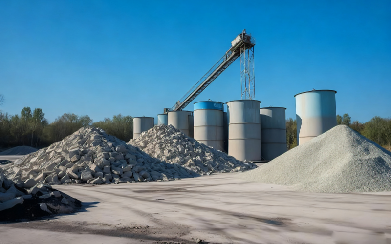
Granular and bulk materials include grains, sugar, salt, feed pellets, plastic pellets, recycled crushed materials, quartz sand, ceramic granules, ores, glass cullet, wood chips, as well as bulk raw materials conveyed by belt. Their primary distinction from powders lies not only in their larger particle size but also in differences in conveying methods, material layer thickness, impact wear, and the typical dimensions of metallic contaminants.
Magnetic contaminant control should first clarify the objective: whether to intercept fine ferromagnetic particles, remove large ferrous components such as bolts and tools, protect crushers or extruders, or continuously separate magnetic fractions. Different objectives may call for magnetic grates, drawer magnets, bullet magnets, magnetic plates, drums, suspended magnetic separators, or multi-stage combinations; a single magnetic field value cannot substitute for a comprehensive assessment of operating conditions.
Typical Control Points Along the Production Line
- Incoming Materials and Discharge:At pit hoppers, feed chutes, ton-bag entries, and bulk-material inlets, the priority is to prevent external ferrous objects from advancing downstream.
- Storage and Batching:Before and after silo outlets, metering scales, and batching equipment, magnetic contaminants introduced during storage, handling, maintenance, and upstream wear can be controlled.
- Equipment Protection:Before crushers, mills, pelletizers, extruders, injection molding machines, and fine screening units, special attention should be paid to large metal fragments that can cause jams, scratches, or damage.
- Conveying and Transfer:In free-fall chutes, slides, vibratory feeders, belt conveyor heads, and transfer points, magnetic field placement must be coordinated with material velocity, layer thickness, and flow trajectory.
- Finished Products and Return Materials:Before packaging, at the entrance to finished-product silos, and when reworked materials re-enter the line, terminal controls can be installed or used in conjunction with metal detectors.
Four Common Equipment Configurations
Free Fall and Silo Outlets
For relatively stable-flow, medium-sized granular materials, magnetic grates, drawer magnets, or bullet magnets are typically considered first. The spacing of magnetic rods, the number of layers, and internal flow guidance must balance contact opportunities with unobstructed passage; for irregular flakes, wet materials, or situations with strong instantaneous surges, bridging and blockage risks must also be evaluated.
Chutes with Large Contaminants or Significant Impact
Magnetic plates, hump‑style structures, or designs that minimally impede material flow are more suitable for addressing large ferrous items, clumps, and abrasive materials. Whether to adopt automatic cleaning depends on the amount captured, the cleaning cycle, continuous‑production requirements, and the location of iron discharge.
Continuous Processing and Automatic Iron Removal
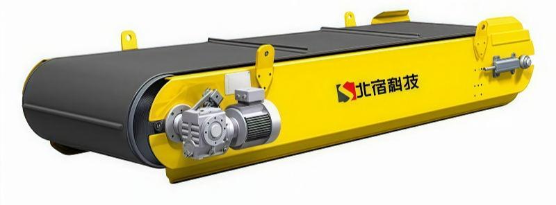
When material throughput is high, magnetic impurities are abundant, or frequent shutdowns are impractical, magnetic head pulleys, drum magnetic separators, or automated‑cleaning systems may be considered. Continuous iron removal does not guarantee consistent separation results under all conditions; feed uniformity, particle size, moisture content, and the material’s behavior within the magnetic field still require verification.
Belt Conveyors and Heavy‑Load Transport
Large ferrous objects on belts are typically handled with suspended permanent‑magnet or suspended electromagnetic solutions, or with magnetic head pulleys at the belt head. Selection should account for belt width, belt speed, material layer thickness, installation height, material density, and the target ferrous object size; site steelwork, idlers, and other ferromagnetic components also influence installation.
Key Variables Requiring Joint Confirmation
- Particle size range, maximum fragment size, material shape, bulk density, and hourly throughput.
- Free fall, belt conveyance, chute flow, or vibratory feeding modes, along with transient surge conditions.
- Moisture content, stickiness, temperature, dust levels, abrasiveness, and corrosiveness.
- Material, size, form, origin, and acceptable residual risk of target metals.
- Cleaning frequency, continuous iron removal, PLC integration, maintenance access, and safety‑protection requirements.
Possible Combination Approaches
A production line might employ a tiered strategy: “intercept large ferrous objects at the inlet—protect processing equipment—implement fine control before finishing.” Ferrous metals, weakly magnetic impurities, and non‑ferrous metals such as aluminum and copper respond differently physically; if non‑ferrous metals also need to be addressed, metal detection or eddy‑current sorting can be further explored, but sample testing or engineering assessments should be conducted based on particle size, material distribution, and target metals.
Recommendations Before Requesting a Quote
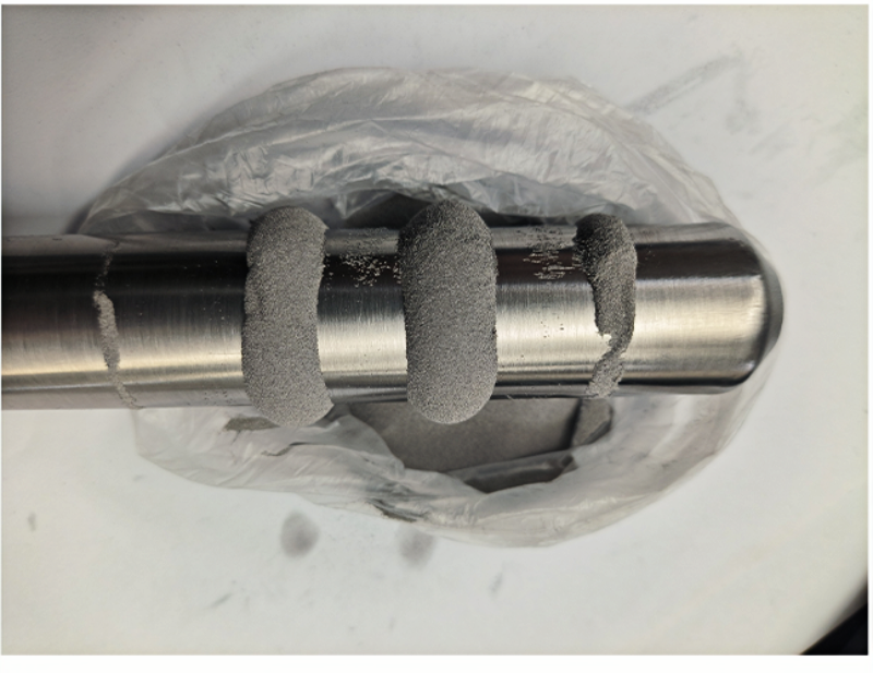
Please provide material photographs, particle size and maximum fragment size, throughput, moisture content, conveying method, interface or belt parameters, samples of metallic impurities, and available on‑site space. Beisu can use this information to help refine equipment placement and conceptual design; final dimensions, materials, magnetic circuits, cleaning methods, and control logic will be confirmed in the technical documentation.
Structural and Principle Diagrams
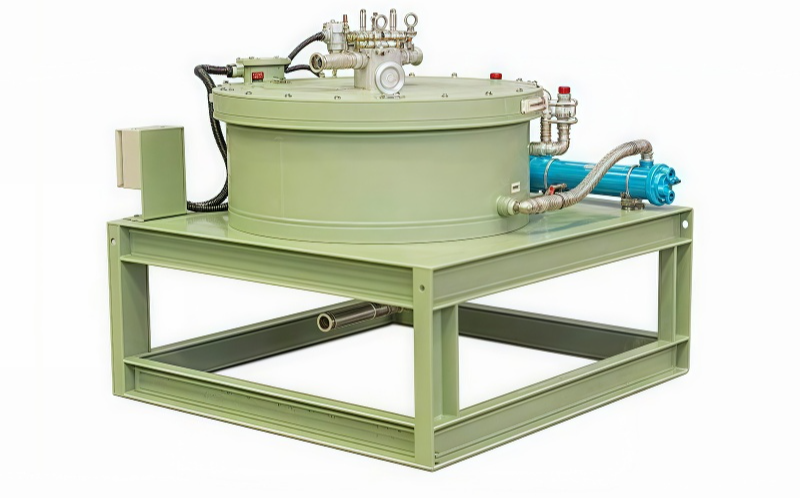
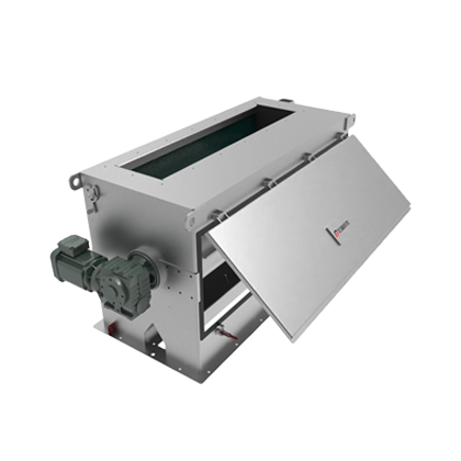
The following are the company’s existing equipment, internal structures, and working‑principle data, intended to aid understanding of applicable configurations, combinations, and installation forms. Final arrangements must still be confirmed in light of material characteristics, throughput, installation space, and cleaning requirements.