Liquid and Slurry Solutions: Start by Assessing the Flow Conditions
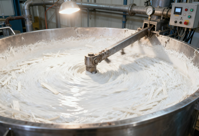
Liquids and slurries do not represent a fixed operating condition. Process liquids with good fluidity, high-solids slurries prone to settling, pastes whose viscosity rises rapidly as temperature decreases, and high-purity materials sensitive to fine, weakly magnetic impurities all require different equipment configurations. When selecting equipment, in addition to the material name, it is also necessary to evaluate viscosity, temperature, solids content, abrasiveness, flow rate, pressure, allowable pressure drop, and cleaning method.
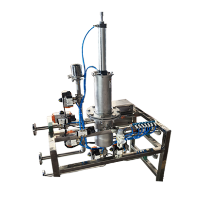
Beisu can begin with permanent magnet pipe separators, tubular slurry magnetic separators, electromagnetic slurry separators, and mobile iron-removal filtration carts, and conduct a comprehensive assessment by integrating functions such as pumps, valves, reflux, backflush drainage, PLC control, jacketed insulation, and metal detection. If standard equipment is unsuitable, further discussions can focus on interfaces, magnetic circuits, flow paths, seals, and control programs.
Key Locations Worth Inspecting in the Production Line
Discharge and Incoming Material Transfer
Before tank cars, IBCs, or raw-material drums enter the storage tank, an incoming-material magnetic filter can be installed to reduce iron filings or rust scale brought in during transport, through connections, and during loading and unloading. Here, it is necessary to confirm the discharge pump, peak flow rate, connection type, and acceptable discharge time.
Storage Tank Outlet and Pre-Pump Protection
The outlet of agitated tanks, reactors, or storage tanks is a common installation location. Placing a separator upstream of the pump primarily aims to capture magnetic contaminants that could damage the pump, valves, and heat exchangers; however, the suction side is more sensitive to pressure drops, and an overly dense structure may compromise pump performance. Whether to install it before the pump should be determined in conjunction with the pump type, net positive suction head, and on-site piping.
Post-Pump Pressure Piping and Process Purification
Piping downstream of the pump facilitates continuous, controllable flow conditions, allowing for consideration of flanged, clamp, threaded, or welded connections. At this location, it is essential to verify the operating pressure, pulsation, flow velocity, the orientation of the magnetic rods relative to the flow, and the space required for equipment maintenance, and to determine the cleaning cycle based on the adsorption load.
Grinding, Dispersion, Mixing, and Circulation
Grinding, dispersion, and mixing equipment may require front-end protection while simultaneously generating new wear particles during operation. For high-value slurries, tank-body reflux or multiple circulation cycles can be employed to pass the material repeatedly through the magnetic separation zone; however, the number of circulation cycles cannot replace stable flow, thorough mixing, and representative sampling.
Filtration, Spraying, Coating, and Pre-Filling
Magnetic filtration near the finished-product end is used to control wear debris from downstream equipment and residual metallic impurities susceptible to magnetic fields. If copper, aluminum, or stainless-steel fragments—non-magnetic metals—also need to be monitored, pipeline metal detection and removal systems can be further evaluated. Magnetic separation and metal detection serve distinct purposes and can be combined based on risk considerations.
Common Technical Approaches
- For fluids with good flowability dominated by ferromagnetic contaminants:Permanent magnet pipe separators with manual or easily cleaned designs.
- For high-viscosity materials prone to wall adhesion or requiring thermal insulation:Optimized flow paths, jacketed structures, lower flow velocities, or recirculation processing.
- For applications with frequent cleaning or hard-to-reach locations:Tubular automatic-cleaning separators with valve isolation, backflush drainage, and PLC interlocks.
- For stringent control of fine or weakly magnetic impurities:Stable feed, electromagnetic slurry separation, high-gradient magnetic media, and sample verification.
- For multi-tank, small-batch, decentralized workstations:Mobile pumping and circulating iron-removal carts.
How to Confirm the Solution Together
It is recommended to provide the material name, the relationship between temperature and viscosity, solids content, particle size, normal and peak flow rates, operating pressure, pipe diameter, contamination levels, installation location, and cleaning requirements. For high-purity or difficult-to-process slurries, sampling methods, pre‑ and post‑sample indicators, and allowable material loss should also be discussed.
Notes:This page outlines the technical directions that can be evaluated. Surface magnetic field values alone cannot fully represent the final capture efficiency; CIP compatibility, explosion-proof ratings, hygiene standards, pressure-handling capacity, and treatment outcomes must all be confirmed on a project‑by‑project basis.
Structural and Principle Diagrams
The following are the company’s existing equipment, internal structures, and working principle documentation, intended to aid in understanding the applicable configurations, combinations, and installation methods. The final configuration must still be validated in light of the material properties, flow rate, available installation space, and cleaning requirements.