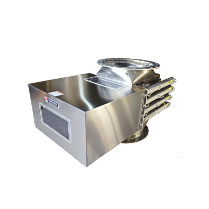
Powder handling solutions are not a single fixed piece of equipment.
Materials commonly referred to as “powders” may range from free-flowing food ingredients to moisture-sensitive, caking chemical powders, or battery and mineral materials with stringent requirements for controlling weakly magnetic contaminants. Equipment selection should not be based solely on the material name; it must also take into account the source of impurities, installation location, flow rate, cleaning method, and validation objectives.
Beisu can start with its existing product lineup—magnetic grates, pipeline magnetic separators, self-cleaning drawer magnets, roller dry magnetic separators—and integrate vibrating feeders, metal detectors, and control systems. When standard configurations are unsuitable, interface designs, magnetic circuits, cleaning mechanisms, and control strategies can be jointly customized.
Key locations in a powder production line worth inspecting
Raw material receiving and unloading
Small-bag filling points, bulk‑bag discharge stations, and bulk‑material receiving areas represent the primary entry points for foreign objects into the production line. At these locations, magnetic grates, drawer magnets, bullet magnets, and subsequent metal detection systems can be considered. When unloading volumes are concentrated, buffer hoppers, uniform feeding, and dust collection also require attention.
Hopper and batching
Hopper inlets are well suited for controlling incoming contamination, while outlets are more effective for protecting weighing, blending, and packaging equipment. For materials with good flowability, static magnetic rod assemblies are appropriate; for hard-to‑access locations or high‑frequency cleaning needs, self‑cleaning options should be evaluated; and in cases prone to bridging, addressing material flow issues should take priority over simply increasing the number of magnetic rods.
Crushing, grinding, and sieving
Mill inlets primarily serve to protect the equipment, with a focus on intercepting large ferromagnetic contaminants such as bolts and metal fragments. Mill outlets, on the other hand, require attention to fine magnetic particles generated by equipment wear; multi‑stage drawer magnets, roller dry magnetic separators, or electromagnetic high‑gradient dry powder processes can be considered. Sieving and stable feeding help ensure that materials enter the magnetic separation zone in a more controlled state.
Mixing, conveying, and packaging
Before blending, control impurities introduced with individual raw materials; after blending, address wear‑generated debris. A final quality check is advisable prior to packaging. Magnetic separators continuously capture ferromagnetic impurities, while metal detectors complement this by identifying both magnetic and non‑magnetic metals; the two serve distinct purposes and can be used in combination.
Common technical approaches
- Free‑fall, good flow:Magnetic grates, drawer magnets, bullet magnets.
- High‑frequency cleaning or hard‑to‑access locations:Self‑cleaning drawer magnets, with iron discharge and interlocks designed according to process requirements.
- Prone to moisture absorption, caking, or bridging:Rotary magnetic separators, larger passage openings, arch‑breaking devices, or vibrating feeders.
- High‑purity dry powders or materials with weakly magnetic components:Stable thin‑layer feeding, roller dry magnetic separation, multi‑stage sorting, or electromagnetic dry powder iron removal.
- When both magnetic and non‑magnetic metals need inspection:Combination of magnetic separators, metal detectors, rejection mechanisms, or machine‑shutdown interlocks.
How solutions are jointly determined
Customers do not need to preselect specific models. By providing the material name, particle size, bulk density, flow characteristics, temperature, normal and peak throughput, impurity profile, installation location, and cleaning requirements, both parties can progressively refine the operating conditions, select the technical approach, confirm interfaces, review the design, and conduct necessary sample‑based validation.
Note:This page outlines potential application scenarios; it does not represent all powder handling applications through a single case study, nor does it guarantee final product purity based solely on the surface magnetic field strength of the equipment.
Structural and principle diagrams
The following materials present the company’s existing equipment, internal structures, and operating principles, serving as references to aid in understanding applicable configurations, combinations, and installation methods. The final configuration must still be confirmed in light of the material properties, flow rate, available space, and cleaning requirements.