Application Scope
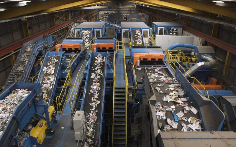
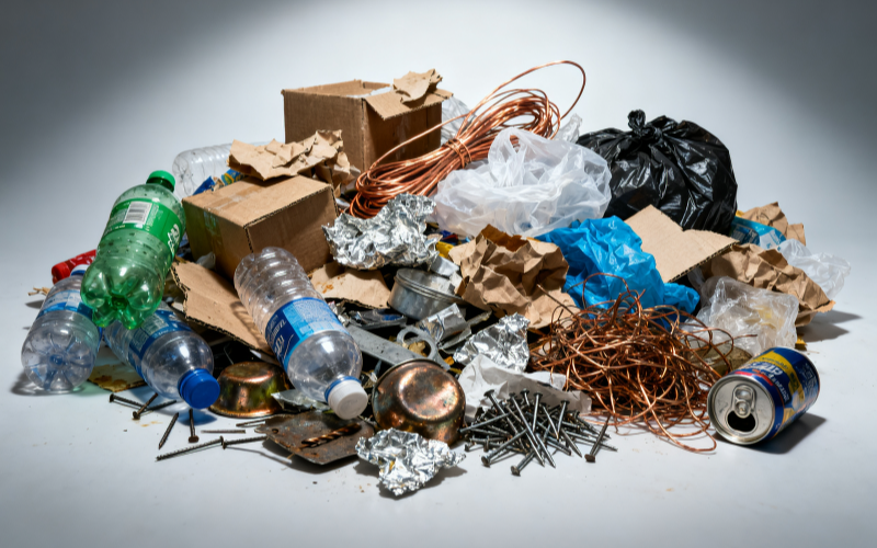
Resource recovery projects typically handle not a single, compositionally stable feedstock, but rather material streams that have undergone dismantling, shredding, screening, or mixed collection. Customers may seek to recover valuable metals such as iron, steel, aluminum, and copper, or they may aim to reduce metallic entrainment in non-metallic product streams like plastics, glass, and wood, while simultaneously protecting downstream equipment, including crushers, screens, conveyors, and subsequent sorting devices.
Different metals exhibit distinct physical responses. Ferromagnetic metals can be prioritized using permanent magnet or electromagnetic equipment; conductive non-ferrous metals such as aluminum and copper can be processed via eddy current separation, depending on particle size and feed conditions; certain stainless steels, fine wires, and composite composites may require alternative detection, sensing, or manual sorting approaches. A complete project should first define the desired product streams before determining the sequence of equipment.
An Assessable Process Chain
- Feedstock and Oversize Control:Identify oversized items,Wrapping material, sealed containers, and hazardous materials to prevent their direct entry into crushing or conveying equipment.
- Shredding and Size Control:Reduce particle size variability through shredding, screening, orGradingto present more consistent material to downstream equipment.
- Stabilized Feeding and Spreading:Vibratory feeders or conveyors regulateInstantaneous flow rate, ensuring the material is spread as uniformly as possible across the working width and minimizing overlap.
- Ferromagnetic Pre-Separation:Suspended magnets, magnetic head pulleys, or drum magnetic separators remove ferromagnetic metals upfront, thereby protecting subsequent belts andHigh-speed rotor.
- Non-Ferrous Metal Sorting:Based on metal conductivity, size, shape, and non-metallic matrix, evaluate routes such as eddy current separation.
- Diversion, Return, and Verification:Adjust diverters and collection methods, inspect each product stream for entrainment,Backmixing, and material loss, and introduce reinspection or return loops as needed.
Why Pre-Treatment Determines Subsequent Performance
ExcessivelyA wide particle size distribution, thickMaterial layer, dampAdhesion, longStrand winding, andInstantaneous material surge can cause target metals to become obscured or move together with other materials. Eddy currentEquipment requires metal particles to developMotion trajectories different from those of non-metals under the influence of an alternating magnetic field; if the material layer overlaps or theThe particle size distribution is excessively broad., even with properly functioning equipment, it may be difficult to achieve aStable productFlow.
Therefore, feeders, screens, and ferromagnetic pre-separation are not auxiliaryEquipmentbut integral components of the entire sorting process. In practice, projects may need to set parameters separately for eachParticle size classand cannot simply use a single set of speed and diversion settings to handle all materials.
Equipment Combination Directions
Large Iron Pieces and Equipment Protection
For belt-fed or heavily loaded feeds, consider suspended permanent magnets, suspended electromagnets, or magnetic head pulleys, focusing on confirming beltWidth,Belt speed,Material layer thickness,Installation height, and theDimensionsof target iron pieces.
Continuous Ferromagnetic Metal Recovery
Magnetic head pulleys, high-intensity magnetic drums, or drum magnetic separators are suitable for continuously separating magnetic andNon-magnetic product streams. The feedingPosition,Material layer,Drum speed, andDividing plate must all be adjusted according to the material.
Conductive Non-Ferrous Metal Recovery
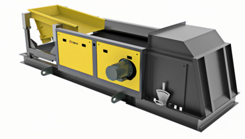
Eddy current separation can serve as anAssessment Routefor conductive metals such as aluminum and copper. The rotor, belt,Feed width, and diversion settings should match theParticle sizeand target metals;Fine particles,Flake-shaped,Linear, orMoisture-containing materials should be verified throughSample material.
Project Evaluation Should Not Rely on a Single Metric
In resource recovery, stakeholders often prioritize metalRecycling, productStream purity, non-metalMaterial loss,Handling capacity, andOperational Stability—objectives that may require trade-offs. Before evaluation, agreed sampling locations, sampling times, weighing or analysis methods should be established, and both the feedstock and each product stream recorded separately, avoiding reliance on a few visual samples to judge the performance of the entire line.
Recommendations Prior to Inquiry
- Photos of the feedstock, composition details,Particle size distribution,Maximum lump size,Moisture content, andBulk density.
- Samples of target metals—iron, steel,Stainless steel,Aluminum,Copper—along with theirDimensionsandApproximate ratio.
- The desired product streams, as well as theEvaluation Methodfor acceptable entrainment and material loss.
- Hourly flow rate, operating schedule, and drawings of existing shredding, screening, and conveying equipment.
- Site space, dust control,Protection,Firefighting,Maintenance and Repair, and controlInterface requirements.
Beisu can assist inCombingequipment combinations and verification sequences based on the above information. The process flows shown on this page are intended as a starting point for discussion and do not constitute a guarantee of fixed performance for any mixed waste stream.
Structural and Principle Diagrams
The following materials present the company’s existing equipment, internal structures, and operating principles to aid in understanding theStructures can be adopted.,combination, and installation forms. The final configuration will stillMust be used in conjunction with the material.,Flow rate,Installation space, andCleaning Method Confirmation.