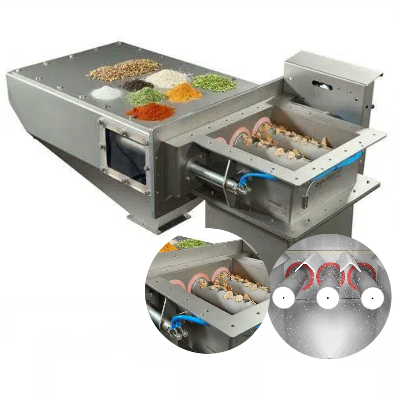
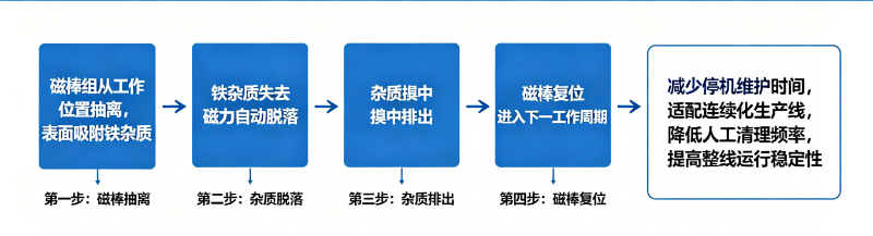
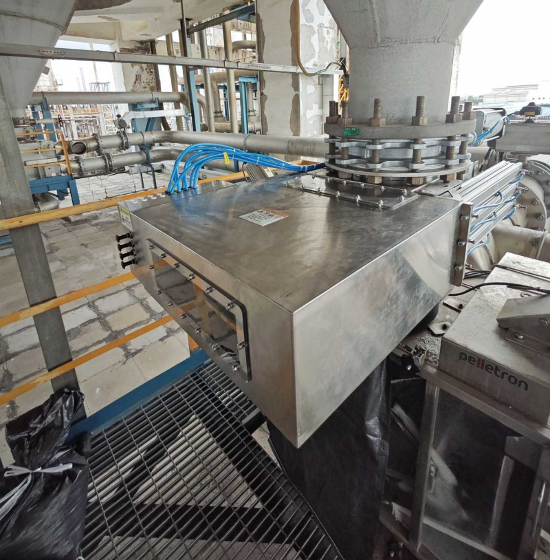
Automatic cleaning drawer magnets switch between the adsorption zone and the iron discharge zone via cylinders, sleeves, or moving magnetic assemblies. This reduces manual pulling and wiping; however, automation truly delivers value only when process isolation, motion confirmation, and the iron discharge path are all clearly defined.
Suitable scenarios for automatic cleaning
Continuous production with limited downtime; rapid accumulation of contaminants; elevated equipment installation or restricted operator access; enterprises that need to integrate the cleaning sequence into the PLC program and log its status. If daily cleaning is infrequent and straightforward, a manual design may prove simpler.
Cleaning operations must be isolated from the material stream
When the magnetic assembly leaves the working position, measures should prevent material from entering the iron discharge channel or passing directly through the non-magnetic area. Common practices include brief material interruptions, installing upstream and downstream valves, or implementing dual-channel switching; the specific sequence depends on the process design.
What feedback signals are required?
At a minimum, confirm the positions of the working and cleaning stations, verify valve statuses, and monitor air pressure or drive malfunctions. The control program must handle timeout events, incorrect positioning, and sudden loss of compressed air to prevent the equipment from stalling in an intermediate state.
Automation does not equate to maintenance-free operation
Regular inspections of cylinders, guide rails, sleeves, seals, and the surface of the magnetic rods remain essential to ensure that removed ferrous contaminants are reliably discharged from the unit. Cleaning intervals should be adjusted based on the amount of accumulated iron rather than fixed at a time independent of operating conditions.
Information recommended for preparation before requesting a quote or conducting sample testing
- Duration of continuous operation and allowable material interruption window
- Contaminant load and current frequency of manual ferrous contaminant removal
- Air supply, electrical control, and upstream/downstream valve specifications
- Requirements for iron discharge collection, dust suppression, and safety interlocks
Note:This document serves to organize common engineering considerations and does not replace technical verification tailored to specific materials, throughput, interface requirements, safety protocols, and cleaning conditions.
Structural and Principle Diagrams
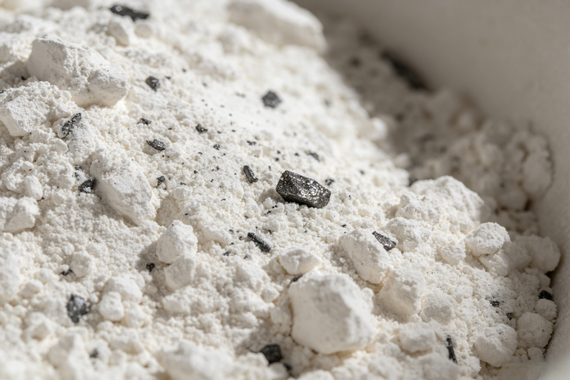
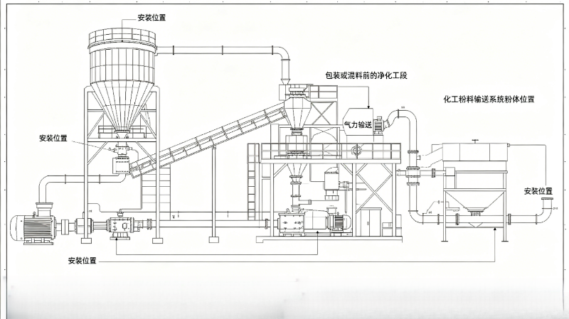
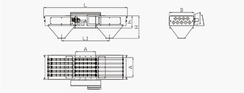
The following materials present the company’s accumulated data on internal structures, components, and operating principles, intended to aid in understanding the technical points discussed herein. Actual configurations and parameters shall be subject to project drawings, sample testing, and selection confirmation results.
No comments yet. You are welcome to share your thoughts.