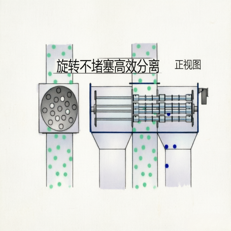
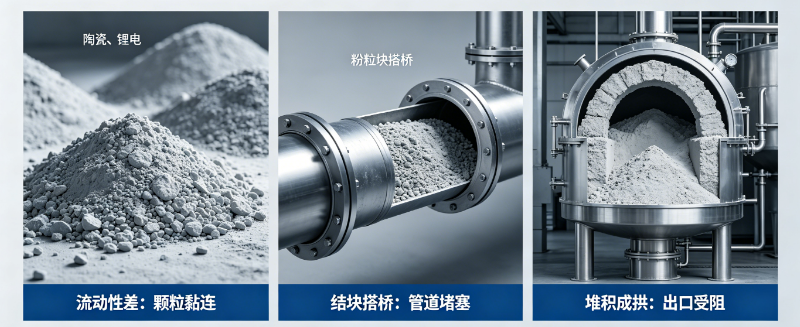
The automatic rotary magnetic separator builds upon low-speed agitation of the material by incorporating an automated cleaning mechanism, making it well suited for powder processing lines where static magnetic rods tend to bridge yet frequent manual shutdowns are undesirable. It integrates both rotational and cleaning functions, with control logic playing an even more critical role than in conventional equipment.
Normal Operation Monitoring
Drive current or torque can be used to detect material blockages. In the event of an overload, first stop the upstream feed, then halt rotation and inspect for foreign objects; do not attempt to resolve the issue by repeatedly forcing startup. Shaft seals, bearing temperatures, and abnormal vibrations should also be included in routine inspections.
How to Trigger the Cleaning Cycle
Cleaning can be initiated based on operating time, batch throughput, or upstream events; where conditions permit, optimization can be further achieved by integrating differential pressure, torque, and accumulated iron deposition data. A cycle that is too short increases the number of actuations and air consumption, while one that is too long may result in the formation of thick layers of collected ferrous contaminants.
Process Isolation During Cleaning
When the magnetic assembly is withdrawn or unloaded, the upstream feed must be stopped or isolated by a valve, and the discharge port must be confirmed open with the collection container properly positioned. Upon completion of cleaning, ensure the magnetic assembly has returned to its working position before resuming feeding.
Safety and Explosion Protection
In dusty environments, assess the risks associated with motors, electrical systems, static grounding, and dust explosions. Before maintenance, perform lockout/tagout procedures, relieve pressure, and prevent unintended startup; automated controls must not replace mechanical safeguards or manual locking.
Information Recommended for Preparation Prior to Quotation or Sample Testing
- Material flowability, moisture content, and maximum agglomerate size
- Throughput, operating shifts, and current frequency of blockages
- Air supply, PLC, valves, and upstream feeding conditions
- Dust control, explosion protection, and requirements for abnormal shutdowns
Note:This document is intended to organize common engineering considerations and does not substitute for technical confirmation tailored to specific materials, production capacity, interface requirements, safety protocols, and cleaning conditions.
Structure and Schematic Diagrams
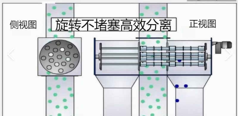
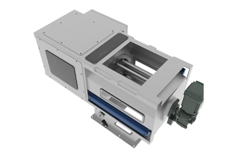
The following materials present the company’s accumulated data on equipment internal structures, components, and operating principles, serving as a reference to aid in understanding the technical points discussed herein. Actual structure and parameters shall be governed by project drawings, sample testing results, and selection confirmation outcomes.
No comments yet. You are welcome to share your thoughts.