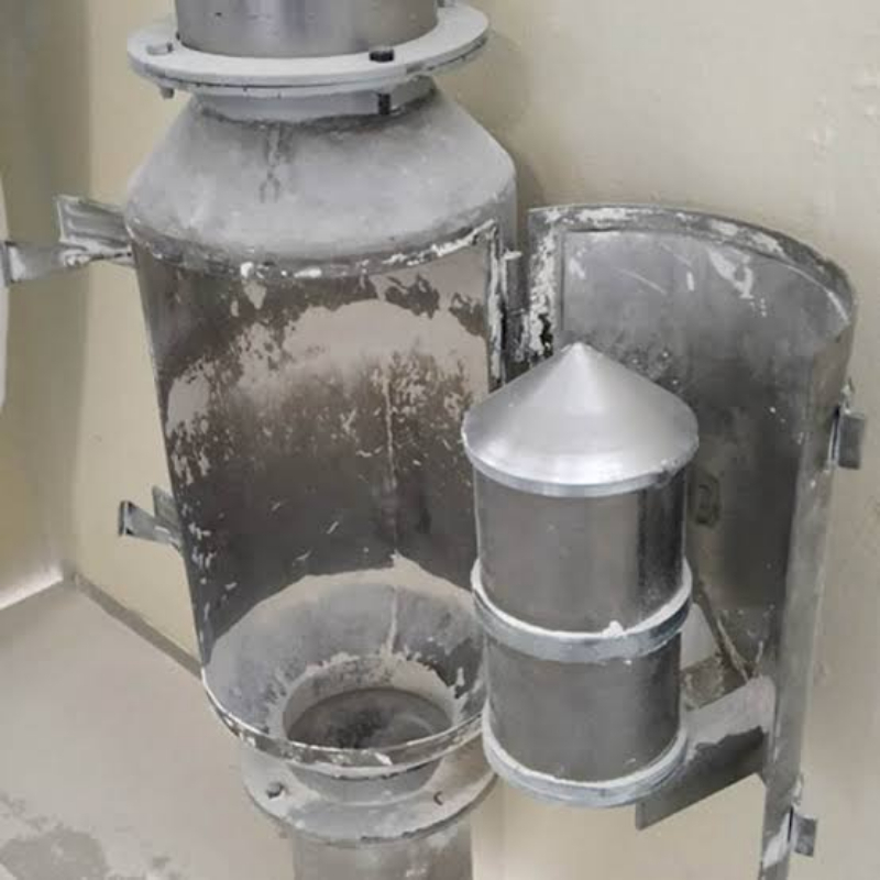
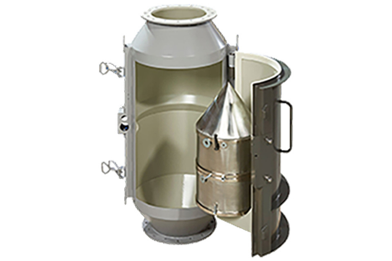
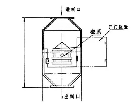
The bullet magnet is typically installed on a vertical or near-vertical free-fall chute. After passing through the flow-directing cap, the material disperses around the central magnetic core, allowing ferromagnetic contaminants to come into close proximity with the magnetic field over a short distance and adhere to the surface of the core.
Suitable materials
Relatively free-flowing powders, grains, feed pellets, and general bulk materials are more likely to form a stable material curtain. Sticky, moist, fibrous, or easily compacted materials may become lodged in the annular channel, necessitating an enlarged passage or the adoption of an alternative design.
Flow guidance: stronger is not always better
The flow-directing cap must spread out the material without causing excessive impact or pulverization. For materials with significant drop heights or high abrasiveness, wear-resistant linings and replaceable impact components should be considered, while avoiding prolonged directFlushing of the magnetic core housing.
Throughput and installation space
Nominal port sizes do not directly indicate the achievable throughput. The effective annular channel should be determined based on bulk density, maximum particle size, instantaneous flow rate, and allowable retention time, while also reserving sufficient clearance for opening the inspection door, removing the magnetic core, and accommodating the collected debris.
Cleaning and inspection
Establish a maintenance schedule according to the amount of accumulated iron; during cleaning, prevent captured contaminants from reintroducing themselves into the product stream. Regularly inspect the magnetic core housing for wear, check for loosening of flow-directing components, and verify the condition of seals and door latches. Upon discovering large ferrous objects, trace their upstream source.
Information to prepare before requesting a quote or conducting a sample test
- Material name, particle size, bulk density, and flow characteristics
- Continuous and peak throughput rates
- Drop height, chute dimensions, and installation orientation
- Degree of abrasiveness and planned cleaning frequency
Note:This document is intended to summarize common engineering considerations and does not substitute for technical confirmation tailored to specific materials, production capacity, interface requirements, safety criteria, and cleaning protocols.
Structural and schematic diagrams
The following materials present the company’s accumulated data on equipment internal structures, components, and operating principles, serving as an aid to understanding the technical points discussed herein. Actual designs and parameters shall be governed by project drawings, sample testing results, and selection confirmation outcomes.
No comments yet. You are welcome to share your thoughts.