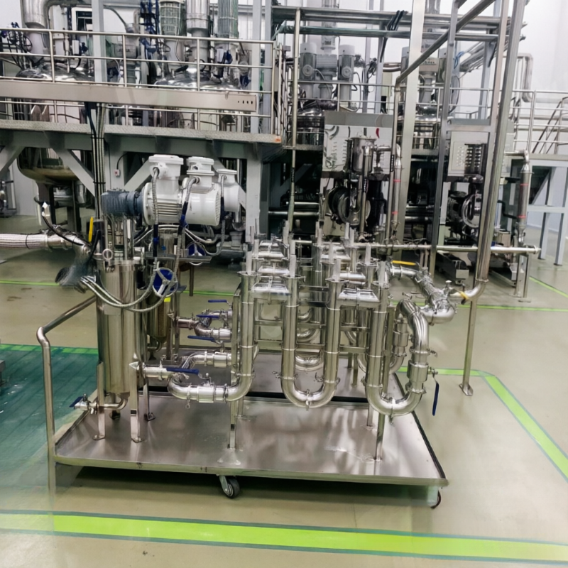
When multiple agitated tanks share a single processing unit, product batches are small, or fixed piping cannot be retrofitted for the time being, the pump, magnetic filter, valves, and hoses can be integrated into a mobile cart to perform bypass circulation on individual storage tanks.
First, define the circulation path
The suction inlet should avoid drawing only bottom sediments or surface clear liquid, while the return outlet must promote overall mixing rather than creating short-circuiting. Where necessary, coordinate with tank agitation and verify the total pressure drop caused by hose length, elbows, and the filter.
Pump–material compatibility
The pump type must be matched to viscosity, solids content, temperature, and shear sensitivity. Installing the magnetic filter upstream of the pump protects the pump but requires controlling the suction-side pressure drop; installing it downstream necessitates selecting the housing, hoses, and fittings based on the maximum system pressure.
Circulation time should not be set empirically
Theoretical circulation cycles depend on tank volume, actual flow rate, and mixing conditions. Samples should be taken at different time points to monitor when key parameters stabilize, and any downtime incurred during magnetic rod cleaning must be included in the total processing time.
Batch change and cross-contamination
When serving multiple products, specify procedures for emptying, disassembly and cleaning, rinsing, and disposal of the initial rinse effluent. Hoses, pump chambers, valves, and magnetic rod sleeves may retain residual material; external surfaces alone are insufficient to clean.
Recommended information to prepare before requesting a quote or conducting trial runs
- Storage tank volume, batch size, and number of tanks
- Medium viscosity, solids content, operating temperature, and shear requirements
- Target flow rate, hose length, and available power supply
- Batch-change cleaning, sampling, and quality-assessment methods
Note:This document is intended to organize common engineering considerations and does not replace technical verification tailored to specific materials, production capacity, interfaces, safety requirements, and cleaning protocols.
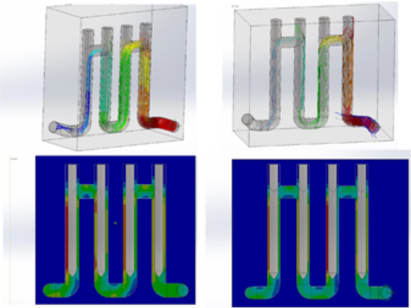
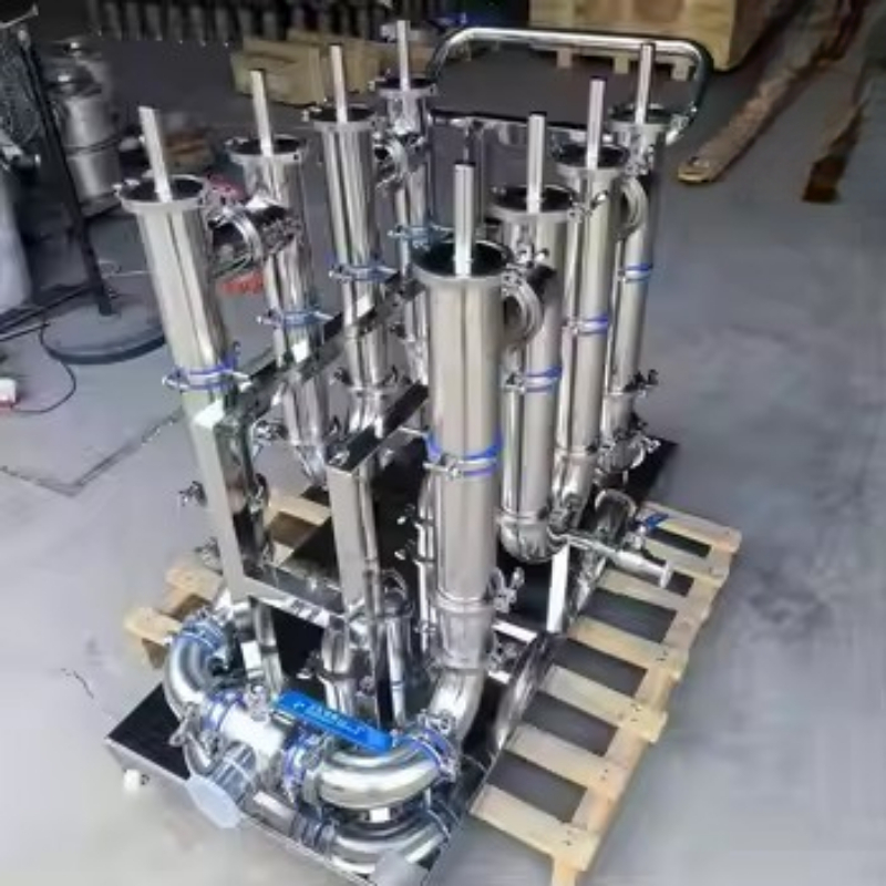
Structural and schematic diagrams
The following are the company’s compiled data on equipment internal structures, components, and operating principles, provided to aid in understanding the technical points discussed herein. Actual configurations and parameters shall be subject to project drawings, sample testing, and selection confirmation results.

No comments yet. You are welcome to share your thoughts.