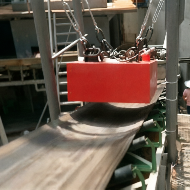
The permanent overband magnet is installed above the conveyor belt to lift ferrous contaminants from ores, aggregates, coal, wood, or recycled materials. It requires no excitation power, but its effective operating distance is fixed, and the installation location must ensure that target ferrous objects are as close as possible to the magnetic field.
Installation at the head and middle sections of the belt
When installed in the head discharge zone, the material remains loosely dispersed, making ferrous contaminants more readily exposed; installation in the horizontal mid‑section of the belt is more convenient, but contaminants may become buried beneath thick layers of material. A comparative analysis should be conducted based on site constraints and material characteristics.
Suspension height is not a fixed value
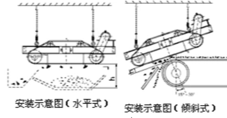
The suspension height should be measured from the working surface of the magnetic poles to the likely position of the target object, rather than simply to the belt surface. The thicker the material layer, the higher the belt speed, and the smaller the target ferrous piece, the greater the difficulty in capture. Setting the height too low, however, may result in collisions with oversized material.
Manual vs. continuous iron removal
When contaminant levels are low and downtime is permissible, a manually cleaned permanent magnet design may be suitable; for continuous ferrous contamination or where shutdowns are impractical, a belt‑type self‑unloading mechanism or other continuous iron‑removal methods should be evaluated, along with the design of the iron‑discharge chute and appropriate protective measures.
Applicable limits
Overband equipment excels at intercepting ferrous objects with strong magnetic response and is not intended as a device for purifying fine powders. For small, weakly magnetic contaminants, the material must be brought closer to a high‑gradient magnetic field.
Information to prepare before requesting a quote or conducting a sample test
- Conveyor belt width, belt speed, trough angle, and material layer thickness
- Maximum lump size and dimensions of target ferrous objects
- Installation location, clearance requirements, and iron‑removal discharge direction
- Ferrous contaminant load, continuous operation duration, and safety protection requirements
Note:This document is intended to summarize common engineering considerations and does not substitute for technical confirmation tailored to specific materials, throughput, interface conditions, safety requirements, and cleaning protocols.
Structural and principle diagrams
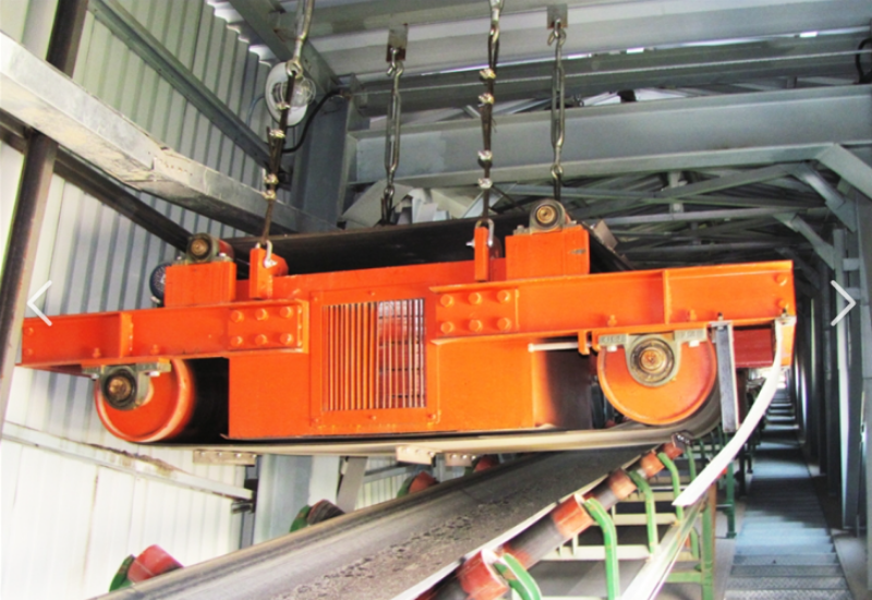
The following materials present the company’s accumulated data on internal structures, components, and operating principles, serving as an aid to understanding the technical points discussed herein. Actual structures and parameters shall be governed by project drawings, sample testing results, and selection confirmation outcomes.

No comments yet. You are welcome to share your thoughts.