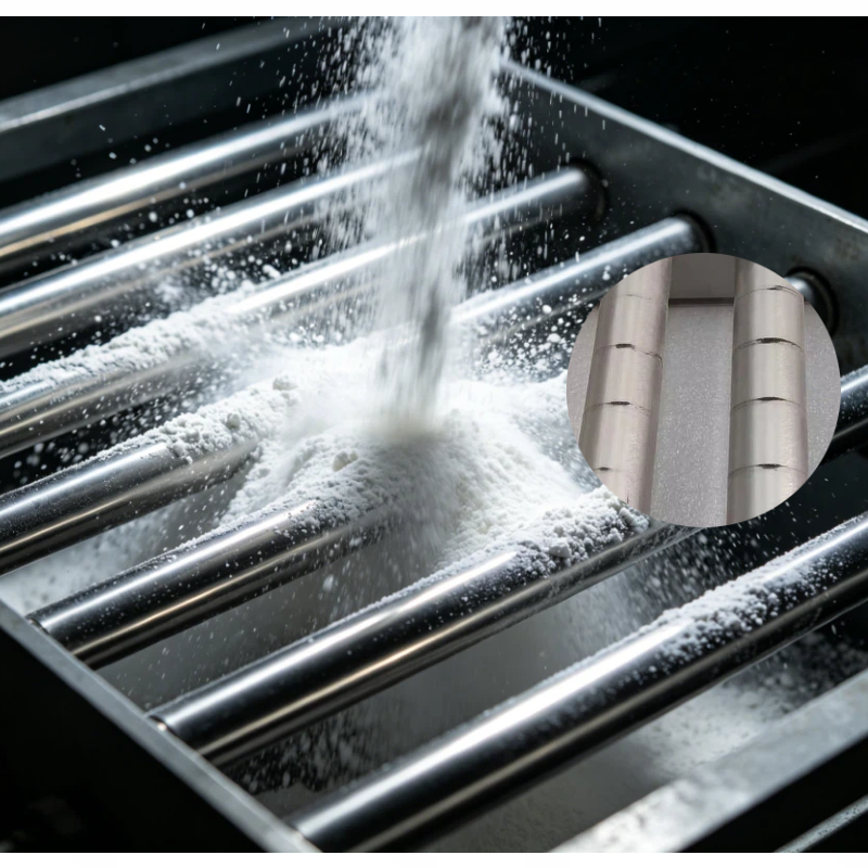
Installing a magnetic grate in the injection molding machine hopper aims to capture iron filings and wear particles before the raw material enters the screw. However, the magnetic rods occupy the flow cross-section; if the material contains long scrap, softened pellets, or dust, an improperly chosen design may exacerbate bridging.
First, determine where the blockage is occurring
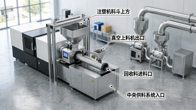
It should be confirmed whether the issue is bridging in the hopper cone, material jamming between the magnetic rods, unstable feeding from the loader, or clumping due to moisture in the raw material. Only ferrous contaminant problems are suitable for treatment with a magnetic grate; flowability issues require simultaneous adjustments to the hopper angle, opening size, vibration, or arch-breaking method.
How to determine the spacing and number of layers of the magnetic rods
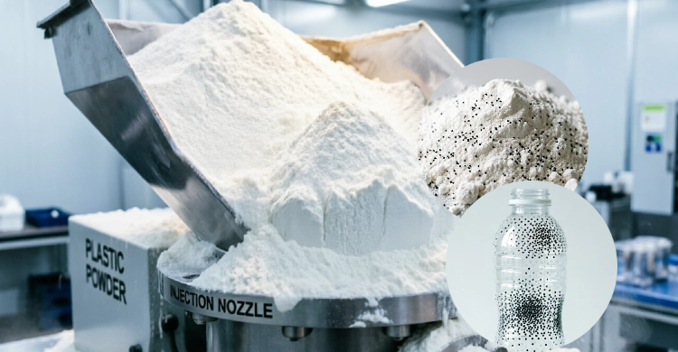
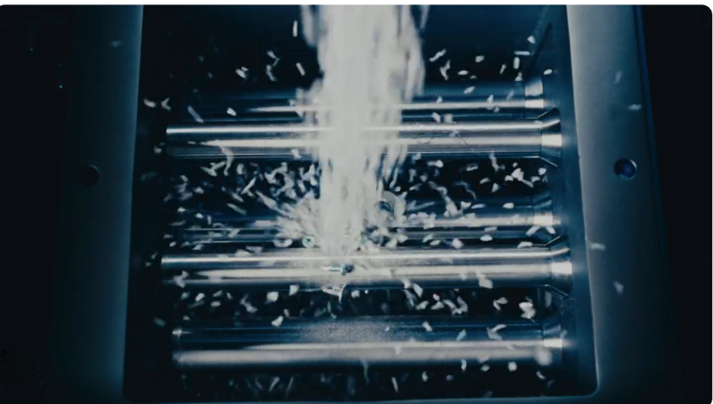
Fine, freely flowing particles can use a denser arrangement of magnetic rods to increase contact opportunities; for irregular scrap or materials containing elongated fragments, the clear spacing should be widened. Staggered multi-layer configurations can enhance capture probability but also increase resistance and cleaning workload, so sufficient effective open area must be provided.
Installation location and maintenance
Prioritize locations that allow easy removal, enable observation of accumulated iron, and prevent cleaned debris from falling back into the hopper. During initial operation, shorten inspection intervals and establish a cleaning cycle based on actual iron accumulation. If a thick layer of contaminants has already formed on the surface of the magnetic rods, subsequent capture efficiency and material throughput will both decline.
When to consider a rotary structure
If the material is prone to bridging and a static grate repeatedly becomes clogged, a rotary magnetic separator can be evaluated to maintain material flow through gentle agitation. However, a rotating mechanism is not a universal arch-breaker; in cases of excessive moisture, severe adhesion, or the presence of large foreign objects, the material condition must still be addressed first.
Information to prepare before requesting a quote or conducting a trial run
- Proportions of virgin and recycled materials, as well as the maximum particle size
- Hourly material consumption and hopper outlet dimensions
- Location and frequency of blockages, along with the material’s moisture content
- Allowable downtime for cleaning
Note:This document is intended to organize common engineering considerations and does not replace technical verification tailored to specific materials, production capacity, interface requirements, safety standards, and cleaning conditions.
Structural and Principle Diagrams
The following are the company’s compiled materials on equipment internal structures, components, and operating principles, used to support understanding of the technical points discussed herein. Actual structures and parameters shall be subject to project drawings, sample testing, and selection confirmation results.
No comments yet. You are welcome to share your thoughts.