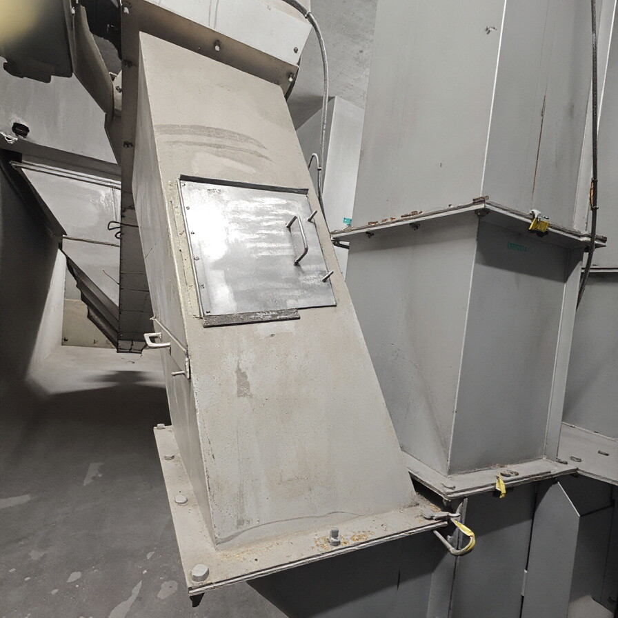
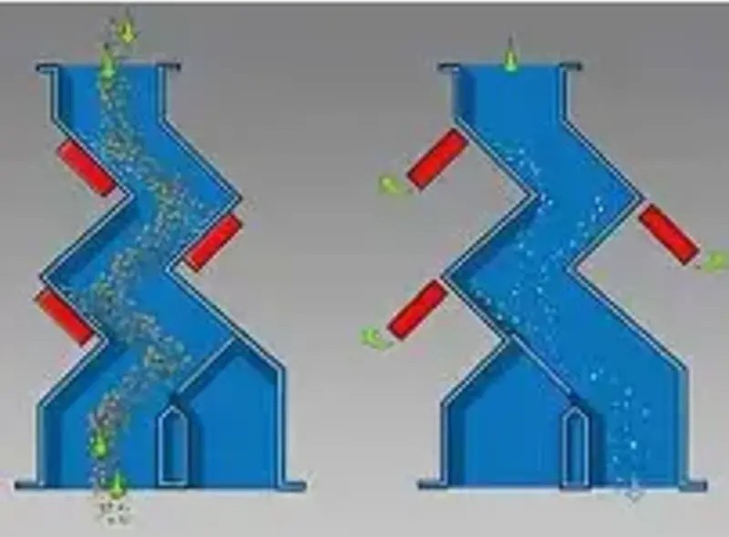
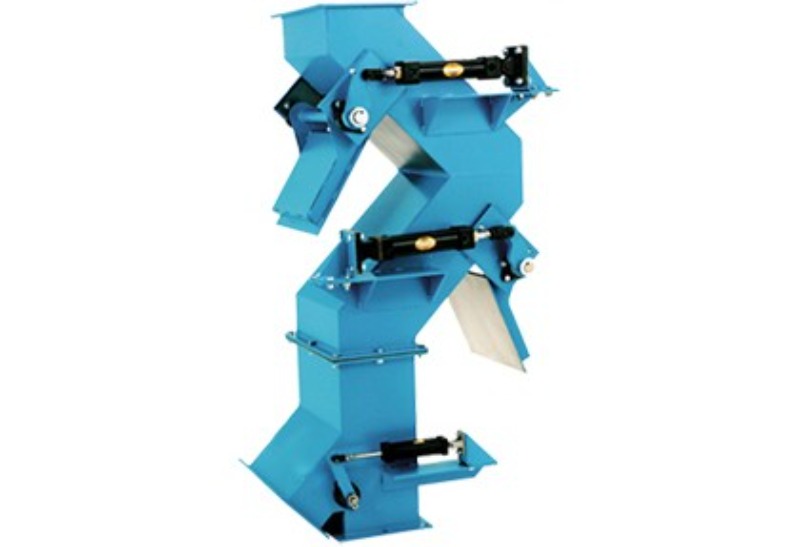
The hump-type pipeline magnetic separator is equipped with two staggered magnetic plates within the housing. The material sequentially impacts or skims across the deflection working surfaces, changing its direction and bringing ferrous contaminants embedded in the flow closer to the magnetic field. This design is suitable for free-falling dry bulk materials, but not all materials are appropriate for forced redirection.
Why redirection is beneficial
In free-fall applications, ferrous contaminants may become entrapped among other particles. As the material strikes and spreads out against the deflector surfaces, the contaminants are more likely to be exposed; the two working surfaces provide two opportunities for capture. However, the effectiveness remains dependent on the material layer thickness, velocity, and the magnetic response of the contaminants.
Wear and impact
Abrasive materials such as minerals and glass cullet continuously scour the deflector surfaces. The wear-resistant construction should be selected based on the drop height, particle size, and throughput, and the thickness of the working surfaces should be inspected regularly to prevent wear-through that could damage the magnets.
Risk of blockage
Moist, sticky materials, long fibers, flaky substances, or large agglomerates may become lodged at the redirection points. During design, verify the minimum passage cross-section and peak flow rates, and if necessary, incorporate inspection ports, vibrators, or adopt a more open configuration.
Limitations of automatic cleaning
While automated systems can reduce the need for manual door opening and cleaning, they cannot eliminate material deposition inside the housing. It remains essential to plan the sequence of feed stoppage, magnetic plate retraction, iron removal, and reset, and to schedule periodic internal inspections.
Information to prepare before requesting a quote or conducting a sample test
- Material particle size, shape, moisture content, and abrasiveness
- Throughput, drop height, and inlet/outlet dimensions
- Target ferrous contaminant size and contamination level
- Requirements for wear resistance, maintenance, and automatic cleaning
Note:This document is intended to summarize common engineering considerations and does not replace the technical confirmation required for specific materials, production capacity, interface conditions, safety requirements, and cleaning protocols.
Structural and principle diagrams
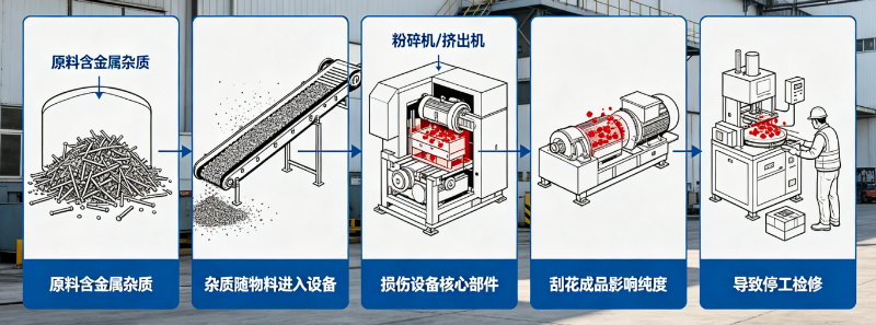
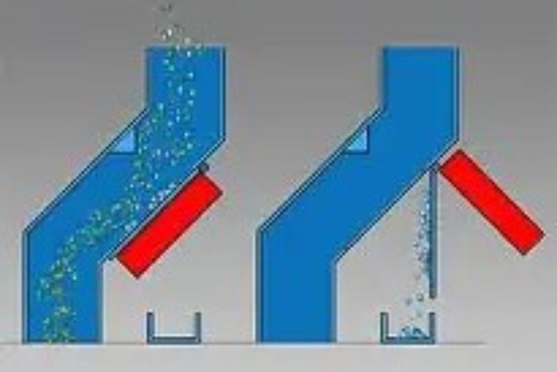
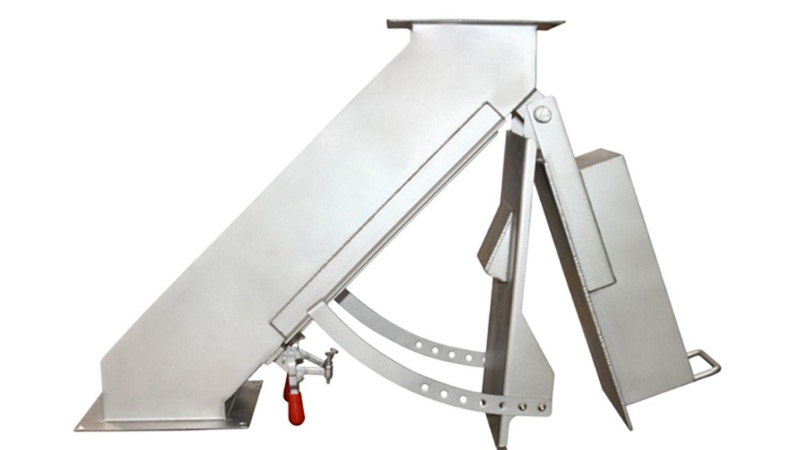
The following materials present the company’s accumulated data on equipment internal structures, components, and operating principles, serving as an aid to understanding the technical points discussed herein. Actual structures and parameters shall be governed by project drawings, sample testing results, and selection confirmation outcomes.
No comments yet. You are welcome to share your thoughts.