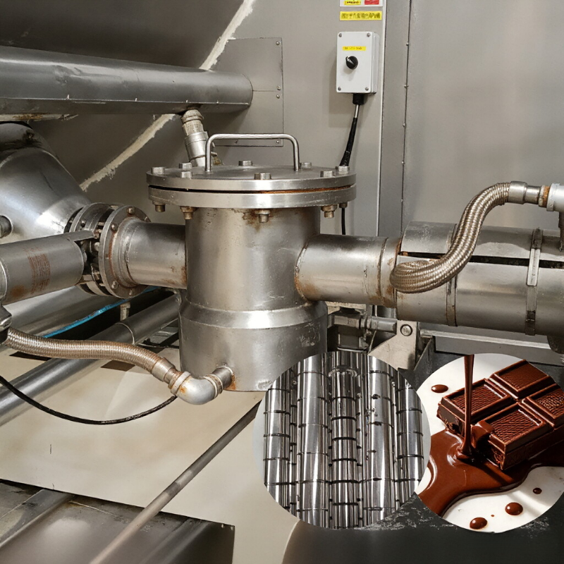
Magnetic rod-based pipeline filters allow liquids or slurries to flow around the magnetic rods, capturing iron filings, rust scale, and fine particles with magnetic responsiveness. The stable operation of the equipment depends on achieving a balance between magnetic capture efficiency and flow resistance.
Flow rate and viscosity determine the channel dimensions
For a given nominal pipe size, the greater the number of magnetic rods and the smaller their spacing, the closer the material is to the magnetic field; however, this also increases pressure drop and the risk of clogging. High-viscosity, high-solids-content, or easily settling materials require larger effective flow passages, and the pump’s available head must be verified accordingly.
Installation upstream or downstream of the pump
Installing the unit upstream of the pump helps intercept ferrous contaminants that could damage the pump; however, the available suction-side pressure differential is limited, and excessive equipment resistance may impair pumping performance. Downstream installation offers higher pressures, but the housing, connections, and seals must be designed to withstand system pressures. The final installation location should be determined by balancing protection objectives with process risks.
Connections, materials, and temperature
It is necessary to specify flange, quick‑connect, or threaded standards, as well as piping orientation and maintenance access. Wetted‑part materials, surface finishes, sealing compounds, and magnet temperature ratings must be compatible with the process medium, cleaning agents, and the maximum operating temperature.
Cleaning method dictates the design
Manually removable‑rod configurations are suitable for applications where downtime can be scheduled and contamination levels are low; for frequent cleaning or continuous production, consider tube‑removal, pneumatic cleaning, or bypass switching. Even so‑called automatic cleaning systems still require careful design of discharge routing, valve sequencing, and cleaning validation.
Information to prepare before requesting a quote or conducting a sample test
- Medium name, viscosity, temperature, and solids content
- Normal and peak flow rates, system pressure, and pump parameters
- Pipe diameter, connection standards, installation orientation, and available space
- Contaminant types, allowable downtime, and cleaning procedures
Note:This document is intended to organize common engineering considerations and does not replace technical confirmation tailored to specific materials, throughput, connections, safety requirements, and cleaning protocols.
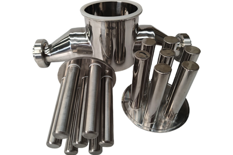
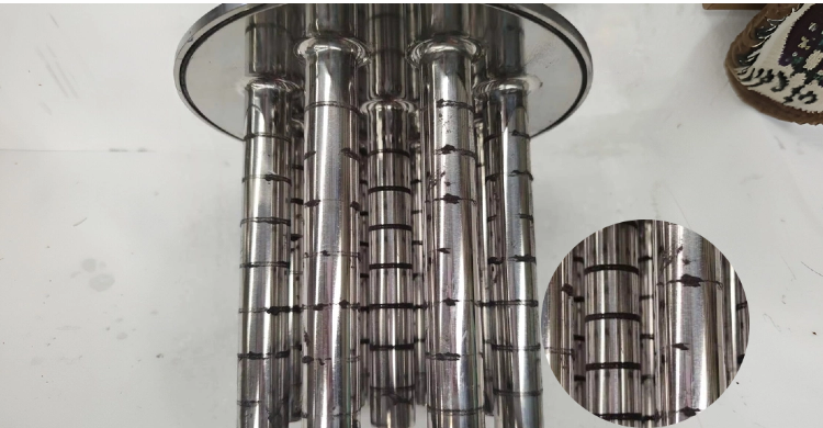
Structural and schematic diagrams
The following are the company’s compiled internal structural layouts, component details, and operational principle data, provided to aid in understanding the technical points discussed herein. Actual structures and parameters shall be governed by project drawings, sample testing, and selection confirmation results.

No comments yet. You are welcome to share your thoughts.