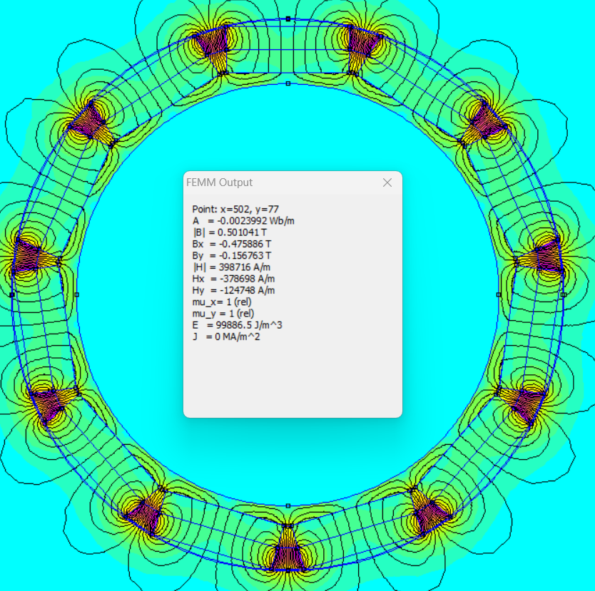
The performance of a drum magnetic separator results from the combined action of the magnetic system, the cylinder, and the feed‑and‑discharge mechanisms. Simply increasing the density of the magnetic blocks or raising the surface magnetic field strength does not automatically translate into better separation; whether ferrous particles are captured promptly, conveyed to the correct position, and discharged smoothly is what truly matters for an accurate evaluation.
The magnetic system must accomplish three tasks simultaneously:
In the feed zone, it must quickly capture the target ferrous particles; in the transport zone, it must maintain sufficient holding force to prevent premature release during material overturning; and in the discharge zone, the magnetic field must decay according to the design, allowing the ferrous particles to enter a discrete product stream. Any misalignment in these zones can lead to missed separations, carry‑over, or re‑entrainment.
Why relying solely on surface gauss values is insufficient
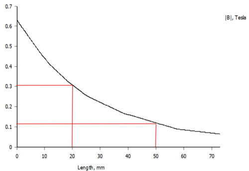
Surface magnetic flux density is merely a point‑measurement. Actual separation is also influenced by the magnetic field gradient, the working distance, the thickness of the cylinder shell, the operating gap, particle size, and belt speed. Under different magnetic circuits, the same surface reading may correspond to markedly different effective adsorption capabilities at varying distances from the cylinder surface.
Design reviews should consider the magnetic field distribution, the effective wrap angle, and the discharge boundary, rather than focusing solely on a single peak value.
Feed and discharge plates can alter the separation outcome
When the material layer is too thick, particles near the bottom get closer to the cylinder surface, while those higher up may be shielded; fluctuations in feed rate can destabilize the separation boundary. The position of the discharge plate likewise requires adjustment based on test runs: placing it too close may increase recovery but also introduce non‑magnetic contaminants, whereas positioning it too far may result in losses of target ferrous particles.
Recommendations for validation
Conduct continuous test runs using representative particle size, moisture content, and impurity levels. Weigh the feed, the magnetic product, and the non‑magnetic reject separately, and record the throughput, belt speed or cylinder rotational speed, and the discharge plate position. In addition to recovery rate, assess product purity, carry‑over levels, and any accumulation that develops over extended operation.
Information to prepare before requesting a quote or conducting a trial run
- Material particle size distribution, bulk density, and moisture content
- Target ferrous particles and acceptable residual levels
- Desired throughput, feeding method, and available installation space
- Whether priority is given to maximizing recovery or improving product purity
Note:This document is intended to summarize common engineering considerations and does not replace detailed technical confirmation tailored to specific materials, production capacity, interface requirements, safety standards, and cleaning conditions.
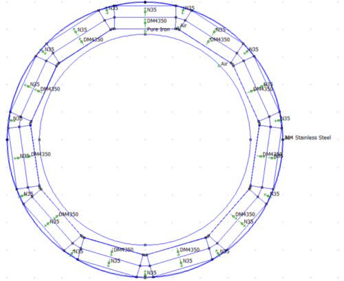
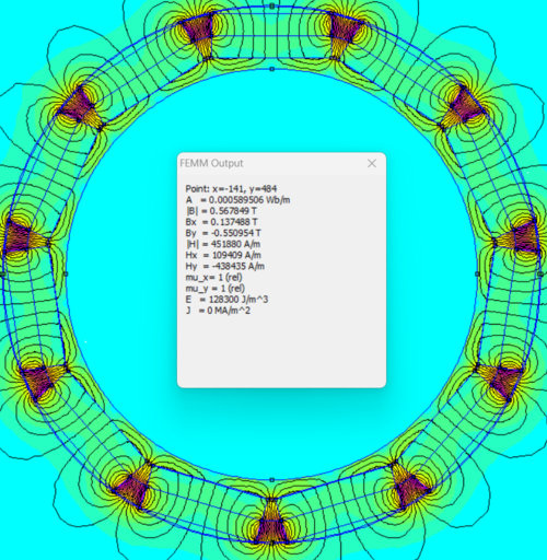
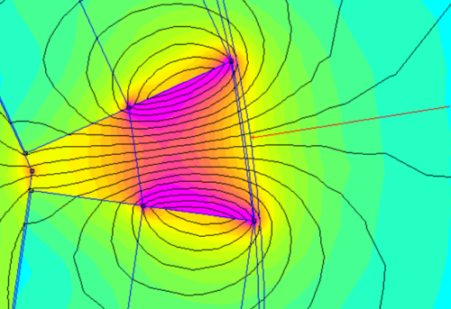
Structural and Principle Diagrams
The following materials present the company’s accumulated data on equipment internal structures, components, and operating principles, serving as an aid to understanding the technical points discussed herein. Actual structure and parameters shall be governed by project drawings, sample testing, and selection confirmation results.
No comments yet. You are welcome to share your thoughts.