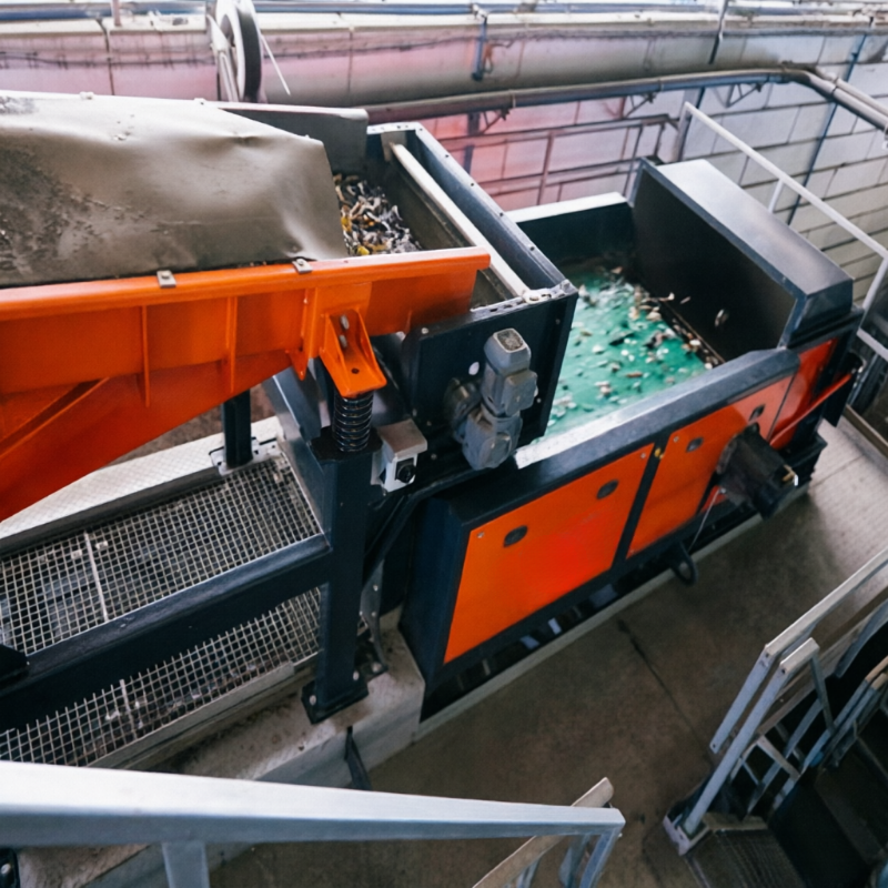
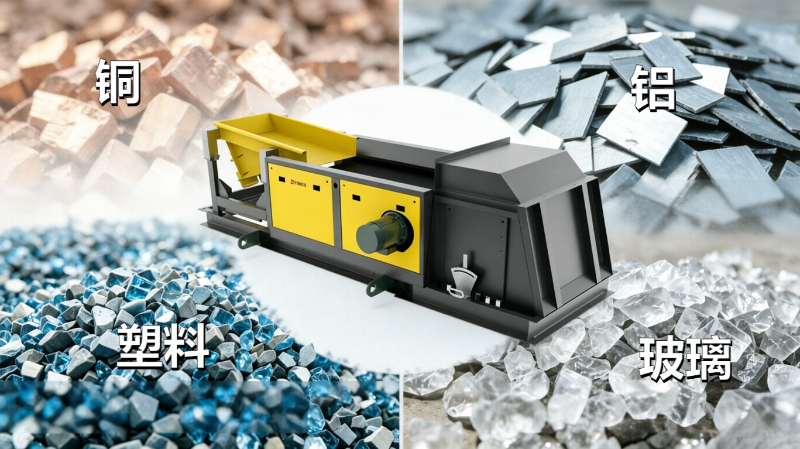
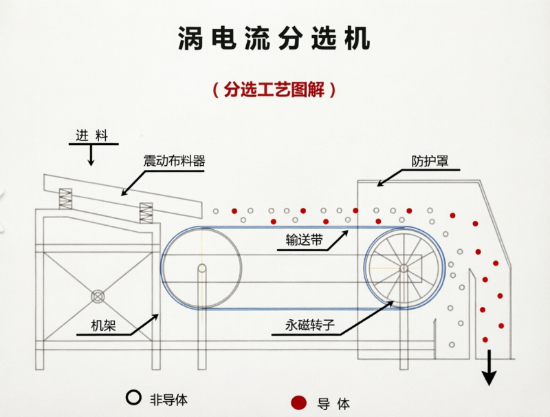
magnetic head pulley ferrous contaminant removal Eddy current separation utilizes a rapidly changing magnetic field to induce eddy currents in conductive non-ferrous metals, causing them to follow trajectories distinct from those of non-metals. When feed conditions are unstable, even with appropriately set machine parameters, carryover and missed separations can occur.
Remove ferromagnetic materials first
Iron pieces are strongly attracted by high-speed magnetic rollers, which may lead to overheating, impact loads, or equipment damage, and can also interfere with material sorting. Typically, ferromagnetic pre-separation is performed using suspended iron removers, magnetic head pulleys, or drum separators.
Why is particle size control necessary?
Materials of different sizes and shapes exhibit varying ejection trajectories. When a broad particle-size distribution enters simultaneously, it becomes difficult to optimize the sorting boundary. Screening to obtain relatively uniform particle sizes is often more effective than repeatedly adjusting the speed of the magnetic roller alone.
Uniformity, single-layer feeding, and stability
Overlapping material layers can obscure non-ferrous metals, causing them to move together with other particles. Vibratory feeders and spreading devices should cover the effective width and strive to form a thin, evenly distributed material layer.
Results are evaluated based on product streams
The mass and composition of the non-ferrous metal stream, the non-metallic stream, and the intermediate return stream are separately analyzed to assess recovery rate, purity, and losses of qualified material. Moist, flaky, and entangled materials require separate validation.
Recommended preparatory information before requesting a quote or conducting trial runs
- Raw material composition, particle-size distribution, moisture content, and particle shape
- Target non-ferrous metal types and minimum particle size
- Ferromagnetic material content and upstream crushing–screening process
- Throughput, equipment width, and target product purity
Note:This document is intended to summarize common engineering considerations and does not replace technical confirmation tailored to specific materials, production capacity, interface requirements, safety, and cleaning conditions.
Structure and principle diagrams
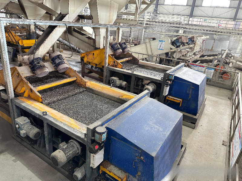
The following materials present the company’s accumulated data on internal equipment structure, components, and operating principles, serving as an aid to understanding the technical points discussed herein. Actual structures and parameters shall be subject to project drawings, sample testing, and selection confirmation results.
No comments yet. You are welcome to share your thoughts.